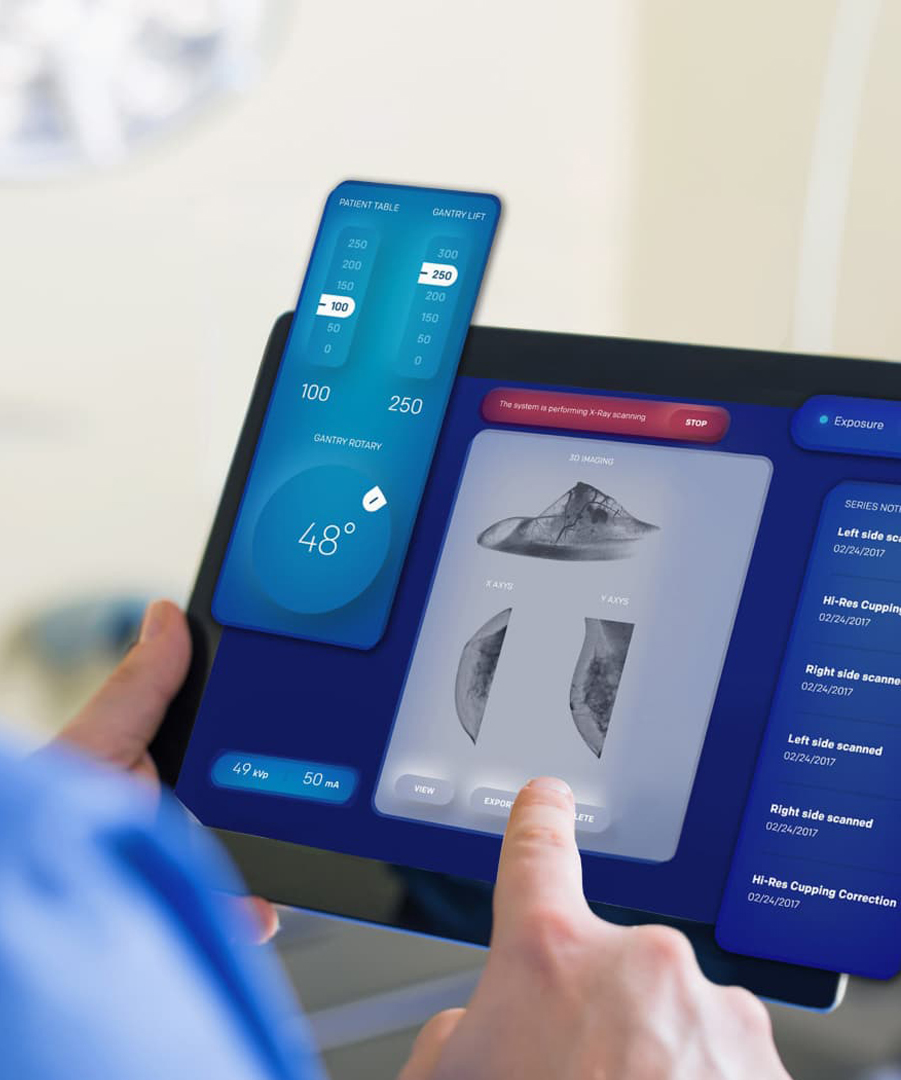
မက်ဆေ့ခ်ျထားခဲ့ပါ
ကျွန်တော်တို့ရဲ့ထုတ်ကုန်တွေကို စိတ်ဝင်စားရင်နဲ့ အသေးစိတ်သိချင်ရင် ဒီမှာမက်ဆေ့ခ်ျထားခဲ့ပါ၊ ကျွန်တော်တို့က အမြန်ဆုံး ပြန်လည်ဖြေကြားပေးပါမယ်။

The fire truck PTO (Power Take-Off) is a power transmission device that transfers engine power to the fire pump. When the firefighter activates the PTO, mechanical power from the engine is transmitted through the transmission and PTO to the fire pump — this is the core working principle of how a fire fighting truck PTO system operates — enabling the pump to deliver high-pressure, high-flow water or foam without the need for a separate auxiliary engine.
Modern fire trucks typically use side-mounted PTO or full power PTO systems. These offer stable power output, convenient operation, and low maintenance costs, making them an essential component of the fire truck's firefighting system.
 Work")
PTO (Power Take-Off) is a critical component in the fire truck's power system. It is a gear transmission device installed between the engine and the transmission, designed to "divert" a portion of mechanical power from the vehicle's engine or transmission to the fire pump or other auxiliary equipment, without affecting the vehicle's normal driving capability.
The fire truck engine is originally responsible only for driving the wheels. However, once the fire truck arrives at the fire scene, the wheels no longer need power, while the fire pump requires power to draw and pressurize water. The PTO is the device that accomplishes this "power switch."

Power Take-Off (PTO) literally means "power output device."
On a fire truck, it refers to extracting rotational power from the engine flywheel or transmission gears through gear engagement, and delivering it to the fire pump or other auxiliary equipment.
Its name describes its function:
Engine = Power source
PTO = Power distributor
Fire pump = Power consumption end
Therefore, the PTO is the bridge connecting the "power source" and the "firefighting system."
The core reason fire trucks must be equipped with a PTO is that firefighting operations require continuous, stable, high-power output that cannot rely on the vehicle's driving state.
Main reasons:
1. Provides continuous firefighting power
The fire pump needs to run for extended periods during firefighting operations. The PTO allows the engine to continuously drive the fire pump at idle or fixed RPM, ensuring stable water pressure and flow.
2. Improves power utilization efficiency
Without a PTO, a separate auxiliary engine would be required to drive the fire pump, which would increase:
Cost
Maintenance complexity
Risk of failure
Space occupation
The PTO directly utilizes the vehicle's engine power, improving overall efficiency.
3. Supports multiple firefighting systems
Modern industrial fire trucks may include not only water pumps but also:
Foam systems
Dry powder systems
High-pressure water systems
Remote-controlled fire monitors
Without a PTO, there are only two solutions:
Install a separate engine to drive the pump → increases weight, cost, maintenance points, and occupies space
Keep the pump permanently connected to the transmission → pump stops when vehicle stops, unable to pump water on site
The PTO solves both problems at once:
| Mode | PTO Status | Power Destination | Result |
| Driving mode | Disengaged | All to wheels | Normal driving |
| Firefighting mode | Engaged | All to fire pump | Pumping while stationary |
The PTO is essentially a "power distribution and conversion system" that transforms vehicle driving power into firefighting operational power.
From an engineering perspective, the complete power path is:
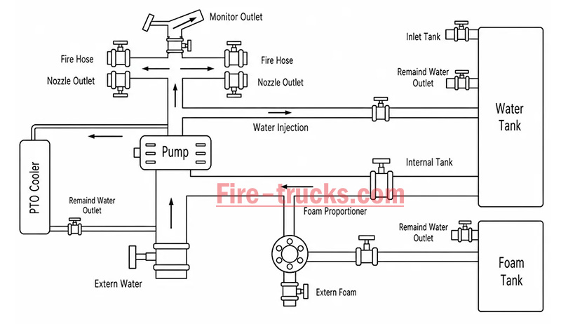
Engine → Transmission → PTO → Drive Shaft → Fire Pump → Fire Monitor/Hose System
The PTO's working principle can be summarized in three key stages: power take-off, engagement, and transmission.
The PTO draws power from the engine. Depending on the installation position, the power take-off method differs:
| PTO Type | Installation Position | Power Source | Characteristics |
| Side-mounted PTO | Transmission side | Transmission countershaft gear | Simple structure, lower power (≤50% engine power) |
| Sandwich PTO | Between engine and transmission | Engine flywheel | Full power output, mainstream configuration |
| Split-shaft PTO | Between transmission and driveshaft | Transmission output shaft | High power, allows pumping while driving |
After the driver presses the PTO switch in the cab, the engagement mechanism activates:
| Engagement Method | Working Principle | Common On |
| Electric solenoid control | Electrical signal activates solenoid, pushing shift fork | Mainstream on modern fire trucks |
| Pneumatic control | Compressed air pushes piston, actuating fork | Large fire trucks |
| Manual cable | Mechanical cable directly pulls fork | Older vehicles |
Operation sequence:
Press PTO switch → Solenoid/cylinder actuates → Shift fork pushes sliding gear → Meshes with flywheel or transmission gear → Power connected
After the PTO output shaft begins rotating, power is transmitted through the drive shaft to the fire pump:
PTO output shaft rotates → Drive shaft → Fire pump input shaft → Pump impeller rotates → Water is pressurized and discharged
| Step | Action | Result |
|---|---|---|
| Step 1 | Engine starts, vehicle idling or driving | Engine running, PTO disengaged |
| Step 2 | Arrive at scene, driver presses PTO switch | Driving power disengaged (on some models), PTO gear activated |
| Step 3 | PTO establishes power connection with transmission | Transmission power is diverted to PTO output shaft |
| Step 4 | Drive shaft transmits power to fire pump | Fire pump begins receiving continuous mechanical power |
| Step 5 | Fire pump impeller rotates at high speed | Suction → Pressurization → Delivery to discharge lines → Firefighting |
| Step 6 | System reaches balanced RPM | Stable output, adjustable pressure, flow, and spray pattern |
The fire truck PTO system is a complete power transmission chain, with multiple components working together to transfer engine power to the fire pump. The system can be broken down into six core components:
The engine is the power source of the PTO system and the heart of the entire fire truck.
Function: Generates raw rotational power, driving the flywheel or crankshaft.
Power output: Typically 300–600 HP (depending on chassis model and configuration).
Relationship with PTO: The PTO draws power from the engine flywheel or crankshaft — it is the starting point of power.
Key characteristic: Engine RPM directly affects PTO output speed and the fire pump's water discharge capability. Fire trucks are typically equipped with high-power diesel engines, which not only drive the vehicle but also provide ample power reserve for the fire pump. After PTO engagement, the operator can control pump discharge pressure by adjusting engine RPM.
The transmission is responsible for power delivery and speed matching.
Function: Receives engine power and adjusts speed and torque through different gear combinations.
Relationship with PTO: Side-mounted PTO draws power from internal transmission gears; sandwich PTO is installed at the front of the transmission.
Key characteristic: Transmission gear position does not affect PTO output speed — PTO operates independently of gear selection.
Two power take-off positions:
Transmission side window take-off: PTO mounted on transmission side, drawing power from countershaft or intermediate shaft gears; common on medium-duty fire trucks.
Transmission rear-end take-off (sandwich): PTO installed between engine and transmission, drawing power directly from the flywheel, enabling full power output.
The PTO is the core of the entire system, responsible for "extracting" power from the engine and delivering it to the fire pump.
Function: Extracts power from the engine or transmission and converts it to the speed and torque suitable for the fire pump.
Installation position: Transmission side (side-mounted) or between engine and transmission (sandwich).
Key characteristic: Determines power transmission efficiency, speed matching, and operational convenience.
The drive shaft is the "power bridge" connecting the PTO and the fire pump.
Function: Transmits rotational power from the PTO output shaft to the fire pump input.
Structure: Typically consists of a metal shaft tube, universal joints, and splined connections.
Key characteristic: Must be precisely aligned to avoid vibration; universal joints allow angular compensation.
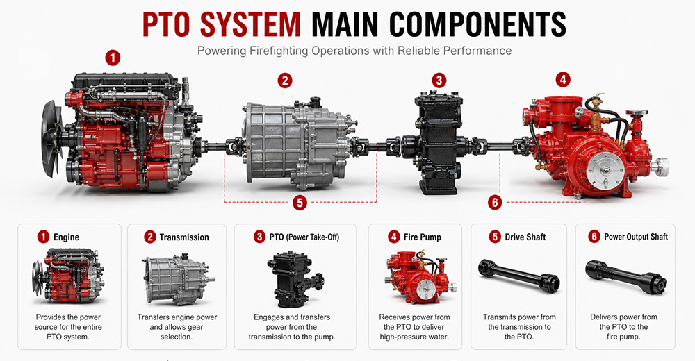
The fire pump is the final load of the PTO system, responsible for converting mechanical energy into water pressure energy.
Function: Receives rotational power from the PTO, drives the impeller to rotate, draws water in, and discharges it under high pressure.
Type: Centrifugal pump (single-stage, two-stage, or multi-stage).
Typical flow rate: 20 L/s – 180 L/s (1,200 – 6,000 L/min).
Typical pressure: 1.0 – 2.5 MPa (10 – 25 bar).
The PTO control system is the "command center" between the driver and the PTO system, responsible for engagement, disengagement, safety protection, and status indication.
Function: Controls PTO engagement and disengagement, monitors system status, and provides safety protection.
Operating location: Cab interior (primary control) and pump panel (auxiliary control).
Control methods: Manual cable, electric solenoid, pneumatic.
Specific control functions:
(1) PTO Engagement Control
The operator presses the PTO switch (electric solenoid/pneumatic) or pulls the lever (manual) in the cab. The control system sends a signal to engage the PTO's internal gears with the power source. After successful engagement is confirmed, an indicator light illuminates, allowing the operator to increase engine RPM.
(2) PTO Disengagement Control
The operator presses the switch again or resets the lever. The control system cuts the signal, and the PTO gears disengage. After disengagement is confirmed, the indicator light turns off.
| PTO Type | Installation Position | Power Source | Power Output | Typical Application |
| Sandwich PTO | Between engine and transmission | Engine flywheel | Full power (≥90%) | Fire pumpers, aerial trucks |
| Split-shaft PTO | Middle of chassis driveshaft | Transmission output shaft | Full power | Large vacuum trucks, airport fire trucks |
| Side-mounted PTO | Transmission side | Transmission gears | Partial power (lower) | Sprinkler trucks, small vacuum trucks |
Sandwich PTO
Advantages: Full power output (≥90%), supports "pumping while driving" (dual-function), high transmission efficiency, easy lubrication.
Disadvantages: Higher cost, complex installation, requires modification to the engine-transmission connection.
Split-shaft PTO
Advantages: Full power output, no additional space required, high reliability, good dynamic balance, can replace auxiliary engine to drive large pumps.
Disadvantages: Requires cutting the original driveshaft, installation position selection must consider driveshaft angle and length compensation.
Side-mounted PTO
Advantages: Low cost, simple installation, can draw power directly from the transmission side.
Disadvantages: Only partial power available, lower output torque, cannot drive high-power fire pumps, mainly used for low-speed, low-power equipment.
 for Fire Trucks")
The process follows a clear mechanical transmission chain:
Engine → PTO → Drive Shaft → Fire Pump → Impeller Rotation → Suction → Pressurization → Fire Monitor
| Factor | Role |
|---|---|
| Centrifugal pump characteristic | When impeller speed is constant, discharge pressure remains naturally stable |
| PTO rigid connection | No slippage or power loss, ensuring continuous stable power input |
| Pressure governor | Automatically detects flow changes and adjusts engine RPM to maintain set pressure |
| Relief valve | Automatically bypasses when pressure exceeds limit, preventing equipment damage |
① Pump speed is determined by engine RPM
Fire pump impeller speed = Engine RPM × PTO ratio. The PTO ratio is fixed (e.g., 1.75:1), so pump speed changes directly with engine RPM.
Calculation formula:
Engine RPM × PTO ratio = Pump speed (RPM)
② Physical relationship between pressure and speed
The pressure generated by a centrifugal pump is proportional to the square of the impeller speed. This physical law means that small changes in RPM cause significant pressure fluctuations.
Speed increases → Centrifugal force increases → Discharge pressure rises
Speed decreases → Centrifugal force decreases → Discharge pressure drops

1. PTO will not engage
Possible causes: Low air pressure (pneumatic type), faulty solenoid, damaged or stuck cable, interlock conditions not met (parking brake not applied, transmission not in neutral).
Solutions: Check air system pressure (must be ≥0.6 MPa); test solenoid; inspect cable; confirm parking brake is applied and transmission is in neutral.
2. PTO engages but pump does not work
Possible causes: PTO clutch failure, broken drive shaft or worn splines, damaged internal gears.
Solutions: Check PTO clutch engagement; inspect drive shaft for breakage or loose connections; disassemble and inspect internal gears.
3. PTO unusual noise
Possible causes: Poor gear meshing or wear, worn bearings, insufficient or degraded lubrication, PTO not fully disengaged.
Solutions: Check gear clearance and tooth wear; inspect bearings; replace with qualified lubricant; confirm PTO is fully disengaged.
4. PTO oil leakage
Possible causes: Worn or deteriorated seals, cracked housing, loose mounting bolts.
Solutions: Replace seals (O-rings, oil seals); inspect housing for cracks; tighten mounting bolts.
5. PTO overheating
Possible causes: Prolonged high-load operation, insufficient or degraded lubricating oil, cooling system failure.
Solutions: Reduce load or shut down for cooling; replace with qualified lubricant; inspect cooling lines.
6. PTO insufficient power
Possible causes: Improper PTO ratio selection, engine RPM set too low, clutch slippage.
Solutions: Confirm PTO ratio matches the fire pump; increase engine RPM to rated operating range; inspect clutch for slippage.
Q1. What does PTO stand for on a fire truck?
PTO stands for Power Take-Off. It is a mechanical system that transfers engine power from the truck's transmission to the fire pump. In simple terms, PTO allows the fire truck's engine to power the pumping system so it can deliver high-pressure water or foam for firefighting operations without needing a separate engine. It is a critical component in industrial and municipal fire trucks.
Q2. Why do fire trucks need a PTO?
Fire trucks need a PTO because it enables the vehicle's main engine to drive the fire pump efficiently. Without a PTO, the fire pump would require a separate engine, which increases cost, weight, and maintenance complexity. PTO systems provide a compact, reliable, and fuel-efficient way to ensure continuous water or foam supply during firefighting operations.
Q3. Can a fire truck operate without a PTO?
Most modern fire trucks cannot operate their pumping system without a PTO because the PTO is responsible for transferring engine power to the fire pump. However, some specialized fire vehicles may use an independent auxiliary engine to drive the pump. These designs are less common due to higher cost, increased maintenance, and lower efficiency compared to PTO-based systems.
Q4. What is the difference between PTO and a fire pump?
The PTO is a power transmission device, while the fire pump is a water or foam pumping system. The PTO delivers mechanical power from the engine to the pump, and the fire pump converts that power into hydraulic pressure to move water or foam. In short, PTO is the "power source connector," and the fire pump is the "firefighting output device."
Q5. How much power can a fire truck PTO provide?
The power output of a fire truck PTO depends on the vehicle design and transmission system. Typically, PTO systems can provide between 50 kW to over 300 kW of mechanical power. Heavy-duty industrial and airport fire trucks often use high-capacity PTO systems capable of supporting large-flow fire pumps and continuous high-pressure operations.
Q6. What are the different types of fire truck PTOs?
There are several types of fire truck PTO systems, including side-mounted PTO, rear-mounted PTO, split shaft PTO, and full power PTO. Side-mounted PTO is commonly used in standard fire trucks, while split shaft and full power PTO systems are used in industrial and airport fire trucks where higher power output and continuous operation are required.
Q7. How do you maintain a fire truck PTO?
PTO maintenance includes regular inspection of lubrication oil levels, checking for leaks, tightening mounting bolts, and ensuring proper alignment of the drive shaft. Operators should also test engagement and disengagement functions regularly. Preventive maintenance is essential to avoid overheating, mechanical wear, and unexpected failure during emergency operations.
Q8. What causes a fire truck PTO to fail?
Common causes of PTO failure include insufficient lubrication, worn gears, misalignment of the drive shaft, overheating, and improper operation by the driver. Electrical or hydraulic control system failures can also prevent PTO engagement. Regular maintenance and correct operating procedures significantly reduce the risk of PTO failure.
Q9. Which PTO is best for industrial fire trucks?
For industrial fire trucks, the best option is usually a split shaft PTO or full power PTO system. These systems can handle high power output, continuous operation, and large-capacity fire pumps. They are widely used in petrochemical plants, refineries, airports, and large industrial facilities where reliable and long-duration firefighting performance is required.
Q10. What should buyers consider when choosing a fire truck PTO?
Buyers should consider engine power compatibility, required fire pump flow rate, vehicle type, and working environment. It is also important to evaluate PTO durability, cooling performance, maintenance accessibility, and compatibility with the chassis. For export projects, compliance with international standards and local regulations should also be taken into account to ensure approval and operational reliability.
PTO (Power Take-Off) is the core system that transfers engine power to the fire pump — it determines whether the entire firefighting system can operate properly.
The fire truck power chain is: Engine → Transmission → PTO → Drive Shaft → Fire Pump → Fire Monitor. Any weak link in this chain affects final firefighting performance.
The primary function of the PTO is to provide stable, continuous mechanical power output, enabling the fire truck to deliver efficient water or foam supply without requiring a separate engine.
Different PTO types (Side-mounted, Rear-mounted, Split shaft, Full power) are suited to different fire truck classes. Industrial fire trucks typically prioritize high-power PTO systems.
PTO performance must match the fire pump flow rate and vehicle chassis, otherwise issues such as insufficient power, unstable pressure, or system overload may occur.
Regular PTO system maintenance (lubrication, tightening, alignment inspection) is key to ensuring reliable fire truck operation, especially in high-intensity industrial applications.
When purchasing industrial fire trucks, buyers should not focus solely on price. PTO power, stability, compatibility, and after-sales support are equally critical factors to evaluate.
For high-risk scenarios such as petrochemical plants, airports, and large industrial parks, Full Power PTO or Split Shaft PTO systems are recommended to ensure continuous operational capability.


အောက်ပါအချက်အလက်များကိုသင်စိတ်ဝင်စားလိမ့်မည်
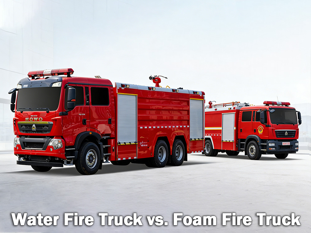
ရေမီးသတ်ကားများ သစ်သား၊ စက္ကူနှင့် အထည်အလိပ်တို့ပါဝင်သည့် သာမန်မီးများကို ငြှိမ်းသတ်ပါ။ ဖော့မီးသတ်ကားများသည် ဓာတ်ဆီနှင့် ဆီကဲ့သို့သော မီးလောင်လွယ်သော အရည်မီးများကို ငြှိမ်းသတ်ကြသည်။ မည်သည့်အရာသည် မှန်ကန်သည်ကို လက်ရှိအန္တရာယ်များပေါ်တွင် မူတည်ပါသည်။ အေ ရေမီးသတ်ကား ရေတိုင်ကီကြီးတစ်လုံးကို သယ်ဆောင်ထားပြီး ရေပိုက်များ သို့မဟုတ် ကုန်းပတ်သေနတ်မှတစ်ဆင့် ရေပို့ရန် မြင့်မားသောဖိအားစုပ်စက်ကို အားကိုးရသည်။ ၎င်းသည် ကမ္ဘာတစ်ဝှမ်းရှိ မြူနီစပယ်မီးသတ်ဌာနများနှင့် စက်မှုလုပ်ငန်းများတွင် အသုံးအများဆုံး မီးသတ်ကားအမျိုးအစားဖြစ်သည်။ အေ ဖော့မီးသတ်ကား အခြားတစ်ဖက်တွင်မူ မီးသတ်အမြှုပ်များကို သယ်ဆောင်ပေးပို့ရန် အထူးဒီဇိုင်းထုတ်ထားသည်။ မီးလောင်လွယ်သောအရည်များ၊ ဓာတုပစ္စည်းများ သို့မဟုတ် လောင်စာဆီမီးများကဲ့သို့သော မီးကို ရေတစ်ခုတည်းဖြင့် ထိရောက်စွာ မငြိမ်းသတ်နိုင်သည့်အခါ အမြှုပ်သည် ပိုကောင်းသောရွေးချယ်မှုဖြစ်သည်။ အမြှုပ်သည် မီးပေါ်တွင် စောင်တစ်ထည်ဖန်တီးခြင်းဖြင့် အောက်ဆီဂျင်ကို ဖြတ်တောက်ပြီး ပြန်လည်မီးမလောင်စေရန် ကာကွယ်ပေးသည်။ I. ရေမီးသတ်ကားဆိုတာ ဘာလဲ။ ရေမီးသတ်ကားဆိုတာ အသံထွက်အတိုင်းပါပဲ။ ရေတိုင်ကီကြီးတစ်ခု၊ အားကောင်းတဲ့စုပ်စက်တစ်ခုနဲ့ မီးလောင်နေတဲ့နေရာတွေကို ရေပို့လွှတ်ဖို့ ရေပိုက်တွေ ဒါမှမဟုတ် စောင့်ကြည့်ကိရိယာတွေ တပ်ဆင်ထားတဲ့ ယာဉ်တစ်စီးပါ။ ရေတိုင်ကီမှာ ဂါလံ ၅၀၀ ကနေ ၃၀၀၀ (လီတာ ၂၀၀၀ ကနေ ၁၂၀၀၀ ခန့်) အထိ ဆံ့ပါတယ်။ စုပ်စက်က ရေတိုင်ကီ ဒါမှမဟုတ် မီးသတ်ရေပိုက်၊ ရေကန် ဒါမှမဟုတ် ရေကန်လိုမျိုး ပြင်ပရင်းမြစ်ကနေ ရေကို ဆွဲယူပြီး မြင့်မားတဲ့ဖိအားနဲ့ ရေပိုက်တွေထဲကနေ တွန်းပို့ပါတယ်။ ရေမီးသတ်ကားများ အကောင်းဆုံးအလုပ်လုပ်သည့်နေရာများ ရေမီးသတ်ကားများသည် အသင့်တော်ဆုံးဖြစ်သည် အမျိုးအစား A မီးများ သာမန်လောင်ကျွမ်းနိုင်သောပစ္စည်းများ ပါဝင်သည်- သစ်သားနှင့် သစ်ခွဲသား စက္ကူနှင့် ကတ်ထူပြား အထည်နှင့်အထည် ရော်ဘာနှင့် ပလတ်စတစ်များ မြက်ခင်း၊ ချုံပင်နှင့် သစ်တောပစ္စည်းများ အိမ်၊ ဂိုဒေါင် သို့မဟုတ် လယ်ကွင်းတွင် လောင်ကျွမ်းသော ပစ္စည်းများပါဝင်ပါက ရေဖြင့် ငြိမ်းသတ်လေ့ရှိသည်။ ရေ၏ ကန့်သတ်ချက်များ- ရေမှာ အဓိကအားနည်းချက်တစ်ခုရှိပါတယ်။ ဓာတ်ဆီ၊ ဆီ သို့မဟုတ် ဓာတုပစ္စည်းများကဲ့သို့သော မီးလောင်လွယ်သောအရည်များပေါ်တွင် ဖြန်းလိုက်သောအခါ ရေသည် ဤလောင်စာများထက် ပိုလေးသောကြောင့် နစ်မြုပ်သွားပါသည်။ လောင်စာသည် အပေါ်မှ ပေါလောမျောနေပြီး ဆက်လက်လောင်ကျွမ်းနေပါသည်။ အချို့ကိစ္စများတွင် ရေသည် မီးကို ပိုမိုကျယ်ပြန့်သောနေရာသို့ပင် ပျံ့နှံ့သွားစေနိုင်သည်။ ထို့ကြောင့် ရေတစ်ခုတည်းသည် မီးလောင်လွယ်သောအရည်မီးများအတွက် အာနိသင်မရှိပါ။ ရေမီးသတ်ကား မီးသတ်စုပ်စက် သတ်မှတ်ချက်များ- ရေမီးသတ်ကား မီးဘေးစောင့်ကြည့်ရေး သတ်မှတ်ချက်များ: II. Foam မီးသတ်ကားဆိုတာ ဘာလဲ။ အမြှုပ်မီးသတ်ကားသည် မီးငြှိမ်းသတ်အမြှုပ်များကို သယ်ယူပို့ဆောင်ရန်နှင့် ပို့ဆောင်ရန် ဒီဇိုင်းထုတ်ထားသော အထူးပြုယာဉ်တစ်စီးဖြစ်သည်။ ၎င်းတွင် ရေအတွက် တိုင်ကီတစ်ခုနှင့် အမြှုပ်အနှစ်အတွက် တိုင်ကီတစ်ခု သီးခြားစီပါရှိသည်။ အမြှုပ်အချိုးကျစနစ်သည် နှစ်ခုကို သတ်မှတ်ထားသောအချိုးအစား၊ ပုံမှန်အားဖြင့် ရေနှင့် ၁%၊ ၃% သို့မဟုတ် ၆% အမြှုပ်အနှစ်အချိုးအစားဖြင့် ရောမွှေသည်။ ထို့နောက် ဤအရောအနှောသည် အမြှုပ်နှုတ်သီးမှတစ်ဆင့် လေထည့်သွင်းပြီး ကျယ်ပြန့်ပြီး တည်ငြိမ်သော အမြှုပ်အလွှာကို ဖန်တီးပေးသည်။ ဖော့မ် ဘယ်လိုအလုပ်လုပ်လဲ- အမြှုပ်များသည် မီးလောင်နေသော အရည် သို့မဟုတ် ပစ္စည်းပေါ်တွင် အလွှာတစ်ခု ဖြစ်ပေါ်စေသည်။ ဤစောင်သည်- မီးအတွက် အောက်ဆီဂျင်ထောက်ပံ့မှုကို ဖြတ်တောက်လိုက်သည် လောင်စာဆီမျက်နှာပြင်ကို အေးစေသည် မီးလောင်လွယ်သေ...
အသေးစိတ်
မီးသတ်ကားများ ရေပေးဝေမှု၊ ဖိအားထုတ်လုပ်ခြင်းနှင့် မီးငြှိမ်းသတ်ခြင်းတို့ကို အောင်မြင်စေရန်အတွက် စနစ်များစွာ၏ ညှိနှိုင်းဆောင်ရွက်မှုလုပ်ဆောင်ချက်မှတစ်ဆင့် လုပ်ဆောင်သည်။ ဤမူများကို နားလည်ခြင်းသည် မီးသတ်တပ်ဖွဲ့ဝင်များအား အရေးပေါ်အခြေအနေများတွင် ထိရောက်စွာလည်ပတ်ရန် ကူညီပေးသည်။ » ၁။ မီးသတ်ကားများ မည်သို့အလုပ်လုပ်ပုံ ▪ A. ပန့်စနစ်- မီးငြိမ်းသတ်ခြင်း၏ အဓိကအချက်- မီးသတ်ကားတိုင်းရဲ့ အဓိကအချက်က ရေစုပ်စက်ပါ။ ဒီစွမ်းအားမြင့်ယူနစ်က မီးသတ်ရေပိုက်ခေါင်း၊ ရေကန် ဒါမှမဟုတ် ရေကန်လိုမျိုး ပြင်ပအရင်းအမြစ်ကနေ ရေကို ဆွဲယူပြီး ဖိအားမြင့်အောက်မှာ ရေပိုက်တွေကနေတစ်ဆင့် ပို့ပေးပါတယ်။ အသုံးအများဆုံးစုပ်စက်ကတော့ centrifugal pump ဖြစ်ပြီး ရေကို ဖိအားပေးပြီး ရွေ့လျားစေဖို့ လည်ပတ်နေတဲ့ impeller ကို အားကိုးပါတယ်။ မီးသတ်သမားများသည် ရေစုပ်စက်ပြားပေါ်ရှိ လီဗာများနှင့် တိုင်းတာကိရိယာများကို အသုံးပြု၍ ရေစီးဆင်းမှုကို ထိန်းချုပ်ကြသည်။ ၎င်းတို့သည် လိုအပ်သလို ဖိအားကို ချိန်ညှိနိုင်ပြီး ရေကို တစ်ပြိုင်နက်တည်း ရေပိုက်လိုင်းများစွာသို့ ပို့ဆောင်ပေးနိုင်သည်။ ပန့်အမျိုးအစား ဝိသေသလက္ခဏာများ အကောင်းဆုံးအပလီကေးရှင်း တစ်ဆင့်တည်းသော ဗဟိုခွာအားသုံး စုပ်စက် မြင့်မားသောစီးဆင်းမှု၊ အလယ်အလတ်ဖိအား အထွေထွေ မြို့နယ်မီးသတ် နှစ်ဆင့် centrifugal pump ထုထည်နှင့် ဖိအားကြား ပြောင်းလဲနိုင်သည် မြင့်မားသော အဆောက်အအုံများ၊ ရှည်လျားသော ရေပိုက်များ ခင်းကျင်းထားသည် ဘက်စုံအဆင့်စုပ်စက် ဖိအားအလွန်မြင့်မားခြင်း စက်မှုလုပ်ငန်းသုံး အဆောက်အအုံများ၊ အမြှုပ်စနစ်များ ▪ အဓိက ပန့် ကန့်သတ်ချက်များ- › ရေစီးဆင်းမှုနှုန်း- တစ်မိနစ်လျှင် ၁၂၀၀ - ၆၀၀၀ လီတာ (မော်ဒယ်ပေါ်မူတည်၍) › အများဆုံးဖိအား: 1.0 - 2.5 MPa (10-25 bar) › အားဖြည့်ချိန်: ≤30 စက္ကန့် ▪ ခ။ ရေတိုင်ကီနှင့် သိုလှောင်စနစ် › တိုင်ကီပမာဏ- ယာဉ်အရွယ်အစားနှင့် အမျိုးအစားပေါ် မူတည်၍ ၅၀၀ မှ ၁၅၀၀ ဂါလံ (ခန့်မှန်းခြေအားဖြင့် ၂၀၀၀ မှ ၆၀၀၀ လီတာ) › တိုင်ကီပစ္စည်း- ချေးခံနိုင်သော သံမဏိ သို့မဟုတ် အလွှာပါးဖုံးအုပ်ထားသော ကာဗွန်သံမဏိ › အတွင်းပိုင်း ဘန်ဖယ်များ- အရေးပေါ်တုံ့ပြန်မှုအတွင်း ရေရွေ့လျားမှုကို ထိန်းချုပ်ရန် ရေလှိုင်းဒဏ်ကာကွယ်သည့် ဒီဇိုင်းပါရှိသော အခန်းများစွာ › ဖြည့်ချိန်- မီးသတ်ရေပိုက် သို့မဟုတ် ရေဖြန်းစက်မှတစ်ဆင့် ≤၃ မိနစ် › ရေအဆင့်ညွှန်ပြချက်- တိုင်ကီဘက်ခြမ်းရှိ မြင်သာသော gauge; ရွေးချယ်နိုင်သော cab display တိုင်ကီကို ချေးခံနိုင်ရည်ရှိသော ပစ္စည်းများ၊ ပုံမှန်အားဖြင့် သံမဏိ သို့မဟုတ် အလွှာပါးဖုံးအုပ်ထားသော ကာဗွန်သံမဏိဖြင့် တည်ဆောက်ထားပြီး အရေးပေါ်တုံ့ပြန်မှု မောင်းနှင်မှုအတွင်း ရေလျှံမှုကို ထိန်းချုပ်ပေးသည့် အတွင်းပိုင်း ဘန်ဖယ်ပြားများ ပါရှိသည်။ ▪ ဂ။ ပိုက်နှင့် နော်ဇယ်စနစ်များ မီးသတ်ကားများသည် မတူညီသောလုပ်ဆောင်ချက်များပါရှိသော ပိုက်အမျိုးမျိုးကို သယ်ဆောင်ထားသည်- › တိုက်ခိုက်ရေးပိုက်- အချင်း ၁.၅ - ၂.၅ လက်မ — မီးရင်းမြစ်သို့ ရေကို တိုက်ရိုက်ပို့ဆောင်ပေးသည် › ပေးဝေရေးပိုက်- အချင်း ၄ - ၅ လက်မ — ရေပိုက်ခေါင်းများ သို့မဟုတ် အခြားစုပ်စက်များမှ ရေကို သယ်ယူပို့ဆောင်ပေးသည် › မြှင့်တင်ပေးသည့်ပိုက်- ရီးလ်ပေါ်ရှိ အချင်းသေးငယ်သည် — မြက်ခင်း သို့မဟုတ် ယာဉ်မီးလောင်ခြင်းကဲ့သို့သော မီးငယ်များအတွက် အသုံးပြုသည် ရေပိုက်၏အဆုံးတွင်၊ နော်ဇယ်သည် မီးသတ်သမားများအား ရေစီးကြောင်းကို ထိန်းချုပ်နိုင်စေပြီး မီးအမျိုးအစားပေါ် မူတည်၍ ဖိအား၊ ပုံစံနှင့် ဦးတည်ရာကို ချိန်ညှိနိုင်စေပါသည်။ ▪ ဃ။ မီးဘေးစောင့်ကြည့်ရေး › ရေစောင့်ကြည့်ကိရိယာ- ကြီးမားသော မီးငြှိမ်းသတ်ရန်အတွက် ရေစီးကြောင်းများစွာကို ပေးပို့သည်။ တပ်ဆင်ပြီး သို့မဟုတ...
အသေးစိတ်
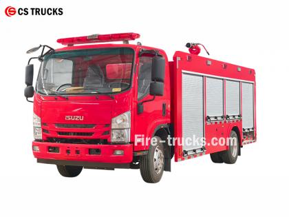
အကျွမ်းကျင်ဆုံး Isuzu မီးသတ်ကားစက်ရုံအနေဖြင့် Isuzu NPR ရေမြှုပ်မီးသတ်ကား၏ အဓိကဒီဇိုင်းမှာ ရေတင်ကားမီးသတ်ကားထဲသို့ ရေမြှုပ်မီးငြိမ်းသတ်စနစ်ကို ပေါင်းစပ်ရန်ဖြစ်ပြီး ရေနှင့် ရေမြှုပ်နှစ်မျိုးလုံးကို ဖြန်းနိုင်သော ပေါင်းစပ်မီးငြိမ်းသတ်ပစ္စည်းကိရိယာတစ်ခု ဖွဲ့စည်းရန်ဖြစ်သည်။ ၎င်းသည် မီးများကို သီးခြားစီငြှိမ်းသတ်နိုင်ပြီး ရေ သို့မဟုတ် ရေမြှုပ်ရောစပ်ထားသောအရည်ကို အခြားပစ္စည်းကိရိယာများသို့ ပို့ဆောင်ပေးနိုင်ပြီး ရေရှားပါးသောနေရာများတွင် လုပ်ငန်းလည်ပတ်ရန်အတွက် သင့်လျော်ပါသည်။ ★ နည်းပညာပိုင်းဆိုင်ရာ သတ်မှတ်ချက် CS ထရပ်ကားများမှ မီးသတ်ကားအားလုံးကို ဖောက်သည်လိုအပ်ချက်များအပေါ် အခြေခံ၍ ၁၀၀% ပြုလုပ်ပေးပါသည်။ စွမ်းရည် အင်ဂျင်မော်ဒယ် ရေ အမြှုပ် မီးသတ်ရေစုပ်စက် မီးဘေးစောင့်ကြည့်ရေး ၂၅၀၀ လီတာ ISUZU 4HK1 / ၁၉ ၀ မြင်းကောင်ရေ ၂၅၀၀ လီတာ ၅၀၀ လီတာ CB10/40 မီးသတ်စုပ်စက် PL8/32 ၂၀၂၆ ခုနှစ်ထုတ် ISUZU မီးသတ်ကား ကိုယ်ထည်ကား ၂၀၂၆ ခုနှစ် မူရင်း မီးသတ်ကား ကိုယ်ထည်ပုံကြမ်း ပစ္စည်း Isuzu မီးသတ်ကားများ၏ ဒီဇိုင်းအသေးစိတ်အချက်အလက်များ ဒီဇိုင်းဗဟို ရေတင်ကား မီးသတ်ကားထဲသို့ အမြှုပ်ငြိမ်းသတ်စနစ်ကို ပေါင်းစပ်ထားပြီး ရေနှင့် အမြှုပ် နှစ်မျိုးလုံးကို ထုတ်လွှတ်နိုင်သော နှစ်ထပ်စွမ်းရည်ရှိသော မီးသတ်ယာဉ်တစ်စီးကို ဖန်တီးပေးပါသည်။ အင်္ဂါရပ်များတွင် အောက်ပါတို့ ပါဝင်သည်- • လွတ်လပ်သော မီးငြှိမ်းသတ်ခြင်း • အခြားပစ္စည်းကိရိယာများသို့ ရေ သို့မဟုတ် အမြှုပ်ရောစပ်မှု ထောက်ပံ့ပေးခြင်း • ရေရှားပါးသော သို့မဟုတ် ရေရှားပါးသောဒေသများအတွက် သင့်လျော်ပြီး ဘက်စုံအသုံးဝင်မှုကို ပေးစွမ်းသည် အလုံးစုံဒီဇိုင်းသဘောတရား အလုပ်ရုံများနှင့် အနီးတစ်ဝိုက်ရှိ မီးငြှိမ်းသတ်ရေးလိုအပ်ချက်များကို ဖြည့်ဆည်းရန် ဒီဇိုင်းထုတ်ထားပြီး ရေနံ၊ လျှပ်စစ်နှင့် အစိုင်အခဲပစ္စည်းများမှ မီးလောင်ကျွမ်းမှုများကို မြှင့်တင်ထားသော စွမ်းရည်များဖြင့် တည်ဆောက်ထားသည်။ ယာဉ်တွင် ကိုယ်ထည်နှင့် အထူးပြုလုပ်ထားသော ကိုယ်ထည်ပစ္စည်းများ ပါဝင်ပြီး ယုံကြည်စိတ်ချရမှု၊ ဘက်စုံလုပ်ဆောင်နိုင်စွမ်းနှင့် လည်ပတ်ရလွယ်ကူမှုကို အလေးပေးထားသည်။ ကိုယ်ထည်ရွေးချယ်မှု • ထိရောက်မှုရှိကြောင်း သက်သေပြထားသော အလတ်စား သို့မဟုတ် လေးလံသော အမျိုးအစား-II ကိုယ်ထည်ကို အသုံးပြုသည် • ရှုပ်ထွေးသော မြေပြင်များတွင် ရွေ့လျားနိုင်မှုနှင့် ဆွဲအားကို ပိုမိုကောင်းမွန်စေရန်အတွက် ဘီးအားလုံးမောင်းနှင်စနစ်ကို အကြံပြုထားသည် ၂၀၂၆ ခုနှစ် ISUZU 700P ရေမီးသတ်ကားများ၏ ဒီဇိုင်းအသစ် အဓိကစနစ် အစိတ်အပိုင်းများနှင့် ဒီဇိုင်း အဓိကအချက်များ ၁။ ရေတိုင်ကီနှင့် အမြှုပ်အရည်တိုင်ကီ • ပစ္စည်း: သံမဏိ၊ ချေးခံနိုင်ရည်ရှိ • အကြံပြုထားသော ပမာဏ- ရေတိုင်ကီ ၃၀၀၀–၅၀၀၀ လီတာ၊ အမြှုပ်အရည်တိုင်ကီ ၃၀၀–၆၀၀ လီတာ • ဖွဲ့စည်းပုံ အကောင်းဆုံးဖြစ်အောင်ပြုလုပ်ခြင်း- အတွင်းပိုင်းအကာများသည် ရေနှင့် အမြှုပ်အခန်းများကို ခွဲခြားထားပြီး၊ ချိတ်ဆက်ထားသော port များမှတစ်ဆင့် ရေတိုင်ကီတစ်ခုတည်းမုဒ်သို့ ပြောင်းလဲနိုင်သောကြောင့် ဘက်စုံအသုံးပြုနိုင်သည်။ ၂။ အမြှုပ်အချိုးကျစနစ် • ရေနှင့် အမြှုပ်အနှစ်ကို ၃% သို့မဟုတ် ၆% အချိုးဖြင့် တိကျစွာ ရောနှောရန်အတွက် ဟန်ချက်ညီသော ဖိအားအချိုးအစား (အဓိကအစိတ်အပိုင်း) ကို အသုံးပြုသည် • စီးဆင်းမှု သို့မဟုတ် ဖိအားအတက်အကျများကြောင့် မထိခိုက်သော တည်ငြိမ်သော အထွက်နှုန်း၊ အထူးကျွမ်းကျင်သူမဟုတ်သော အော်ပရေတာများအတွက် သင့်လျော်သည် • နေရာတွင် ပြန်လည်ဖြည့်တင်းရန်အတွက် ပြင်ပအမြှုပ်စုပ်ယူသည့် ဝင်ပေါက် တပ်ဆင်ထားသည် ၃။ စွန့်ထုတ်စနစ် • မီးသတ်စုပ်စက်- စွမ်းဆောင်ရည်မြင့်မားပြီး စွမ်းအင်ချွေတာသော အဆင့်များစွာပါသော ဗဟိုခွာအားသုံးစုပ်စက်၊ စီးဆင်းမှ...
အသေးစိတ်
PF5-15 ပုံသေခြောက်သွေ့သောအမှုန့်စောင့်ကြည့်ကိရိယာ ခြောက်သွေ့သောအမှုန့်ကို ကြားခံအဖြစ်အသုံးပြုပြီး တည်ငြိမ်စွာပက်ဖျန်းရန်အတွက် အသေခံအခြေခံကို အားကိုးသည်။ ၎င်းသည် ဓာတုဗေဒနှင့် ဂိုဒေါင်ဧရိယာများအတွက် သင့်လျော်ပြီး မီး၏အစောပိုင်းအဆင့်များတွင် မီးလောင်နေသောမျက်နှာပြင်ကို လျင်မြန်စွာဖုံးအုပ်နိုင်သောကြောင့် မီးငြိမ်းသတ်နိုင်စွမ်းကို မြှင့်တင်ပေးပါသည်။ ထို PF5-15 ပုံသေ ခြောက်သွေ့သော အမှုန့် စောင့်ကြည့်ကိရိယာ ခိုင်ခံ့သောဖွဲ့စည်းပုံရှိပြီး လည်ပတ်ရလွယ်ကူကာ အဝေးထိန်းစနစ်ဖြင့် အသက်သွင်းခြင်းနှင့် တိကျစွာဖြန်းခြင်းအတွက် အလိုအလျောက်ထိန်းချုပ်မှုစနစ်နှင့် ချိတ်ဆက်နိုင်သည်။ » ၁။ PF5-15 ပုံသေ ခြောက်သွေ့သော အမှုန့် စောင့်ကြည့်ကိရိယာ ဖွဲ့စည်းပုံ: PF5-15 ပုံသေ ခြောက်သွေ့သော အမှုန့် မော်နီတာ၏ အင်္ဂါရပ်များ- ● အပြည့်အဝလုပ်ဆောင်နိုင်စွမ်းရှိသည်; ● ရိုးရှင်းပြီး ဆန်းသစ်သောဖွဲ့စည်းပုံ; ● တည်ငြိမ်သောစွမ်းဆောင်ရည်နှင့် ပြုပြင်ထိန်းသိမ်းမှုလွယ်ကူခြင်း။ ● ဝင်ပေါက်ဖိအားနည်းခြင်း။ ● အလျားလိုက်နှင့် ဒေါင်လိုက် လော့ချသည့် လုပ်ဆောင်ချက်များပါရှိသော အလိုအလျောက် ရေဆင်းပိုက်အဆို့ရှင် တပ်ဆင်ထားသည်။ ● ပစ္စည်း: တိကျစွာသွန်းလုပ်ထားသော အလူမီနီယမ်အလွိုင်း; ● အမြောက်ခေါင်း: အလူမီနီယမ်အလွိုင်း။ �
အသေးစိတ်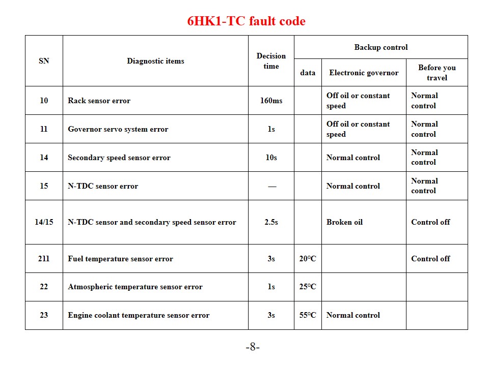
Isuzu 6HK1-TC မီးသတ်ကားများ , ဟုလည်း အမည်ပေးထားသော Isuzu မီးသတ်ကား အင်ဂျင်အမှားကုဒ်ရောဂါရှာဖွေခြင်းနှင့်ဖြေရှင်းချက်များ။ Isuzu 6HK1-TC အင်ဂျင်သည် အဆင့်မြင့် TICS လောင်စာထိုးပန့် အီလက်ထရွန်းနစ်ထိန်းချုပ်မှုစနစ်ကို အသုံးပြုထားပြီး ECU (အင်ဂျင်ထိန်းချုပ်ယူနစ်) တွင် ကိုယ်တိုင်ရောဂါရှာဖွေခြင်း ပါရှိသည်။ စနစ်သည် ချို့ယွင်းချက်ကို တွေ့ရှိသောအခါ "အင်ဂျင်စစ်ဆေးခြင်း" သတိပေးမီးလင်းလာပြီး သက်ဆိုင်ရာချို့ယွင်းချက်ကုဒ်ကို သိမ်းဆည်းထားသည်။ ဤအမှားကုဒ်များအတွက် အဓိပ္ပာယ်ဖွင့်ဆိုချက်နှင့် ဖြေရှင်းချက်များကို နားလည်ခြင်းသည် အင်ဂျင်ပြုပြင်ထိန်းသိမ်းမှုစွမ်းဆောင်ရည်ကို ထိရောက်စွာတိုးတက်စေနိုင်သည်။ အဖြစ်များသော အမှားကုဒ်များနှင့် ဖြေရှင်းချက်များ P-စီးရီး ပြဿနာကုဒ်များ P0101 (Mass Air Flow Sensor ဆားကစ် နိမ့်နေ) အင်ဂျင်အအေးခံအပူချိန်အာရုံခံကိရိယာနှင့် ၎င်း၏ဝါယာကြိုးများကို စစ်ဆေးပါ။ အာရုံခံကိရိယာပါဝါထောက်ပံ့မှုဗို့အားနှင့် မြေပြင်ချိတ်ဆက်မှုကို စစ်ဆေးပါ။ လိုအပ်ပါက ECU သို့မဟုတ် အာရုံခံကိရိယာကို အစားထိုးပါ။ P0102 (လေစီးဆင်းမှု အာရုံခံကိရိယာ ဆားကစ် မြင့်နေ) လောင်စာဆီအရည်အသွေးနှင့် filter အခြေအနေကို စစ်ဆေးပါ။ လောင်စာစနစ်ကို သန့်ရှင်းရေးလုပ်ပါ။ လောင်စာဖိအားထိန်းညှိကိရိယာ၊ လောင်စာပန့်နှင့် injector ဆားကစ်များကို စစ်ဆေးပါ။ P0103 (Mass Air Flow Sensor A ဆားကစ် မြင့်နေ) အာရုံခံကိရိယာအချက်ပြဆားကစ်တွင် ရှော့ပတ်လမ်းရှိမရှိ စစ်ဆေးပါ။ အာရုံခံကိရိယာ၏ လည်ပတ်မှုအခြေအနေကို စမ်းသပ်ပါ။ လိုအပ်ပါက အာရုံခံကိရိယာ သို့မဟုတ် ECU ကို အစားထိုးပါ။ ဒစ်ဂျစ်တယ်ပြဿနာကုဒ်များ ၁၀ (ရက်ခ် အာရုံခံကိရိယာ အမှား) ရက်ခ် အာရုံခံကိရိယာနှင့် ၎င်း၏ ဝါယာကြိုးများကို စစ်ဆေးပါ။ ပုံမှန် အချက်ပြမှု ထုတ်လွှင့်မှုကို အတည်ပြုပါ။ ၁၁ (မြန်နှုန်း အုပ်ချုပ်ရေးမှူး ဆာဗိုစနစ် အမှား) မြန်နှုန်းထိန်းချုပ်ကိရိယာ servo စနစ်၏ လည်ပတ်မှုအခြေအနေကို စစ်ဆေးပါ။ ဆက်စပ်နေသော ဆားကစ်ချိတ်ဆက်မှုများကို စမ်းသပ်ပါ။ ၁၄ (အရန် မြန်နှုန်း အာရုံခံကိရိယာ အမှား) အရန်မြန်နှုန်းအာရုံခံကိရိယာ၏ တပ်ဆင်မှုအနေအထားကို စစ်ဆေးပါ။ အာရုံခံကိရိယာ၏ အချက်ပြမှုအထွက်ကို စမ်းသပ်ပါ။ ၁၅ (N-TDC အာရုံခံကိရိယာ အမှား) N-TDC အာရုံခံကိရိယာ ချိတ်ဆက်မှုကို စစ်ဆေးပါ အချက်ပြမှု တိကျမှုကို အတည်ပြုပါ စနစ်ပြုပြင်ထိန်းသိမ်းမှုနှင့် ကြိုတင်ကာကွယ်မှုများ SN ရောဂါရှာဖွေရေးပစ္စည်းများ ဆုံးဖြတ်ချက်ချချိန် အရန်ကူးယူထိန်းချုပ်မှု ဒေတာ အီလက်ထရွန်းနစ် အုပ်ချုပ်ရေးမှူး ခရီးမထွက်ခင် ၁၀ ရက်ခ် အာရုံခံကိရိယာ အမှား ၁၆၀ မီလီစက္ကန့် ဆီမထည့်ပါ သို့မဟုတ် စဉ်ဆက်မပြတ်မြန်နှုန်း ပုံမှန်ထိန်းချုပ်မှု ၁၁ ဂါဗာနာ ဆာဗိုစနစ် အမှား ၁ စက္ကန့် ဆီမထည့်ပါ သို့မဟုတ် စဉ်ဆက်မပြတ်မြန်နှုန်း ပုံမှန်ထိန်းချုပ်မှု ၁၄ ဒုတိယမြန်နှုန်းအာရုံခံကိရိယာအမှား ၁၀ စက္ကန့် ပုံမှန်ထိန်းချုပ်မှု ပုံမှန်ထိန်းချုပ်မှု ၁၅ N-TDC အာရုံခံကိရိယာ အမှား — ပုံမှန်ထိန်းချုပ်မှု ပုံမှန်ထိန်းချုပ်မှု ၁၄/၁၅ N-TDC အာရုံခံကိရိယာနှင့် ဒုတိယမြန်နှုန်းအာရုံခံကိရိယာ အမှားအယွင်း ၂.၅ စက္ကန့် ကွဲနေတဲ့ဆီ ထိန်းချုပ်မှုကို ပိတ်ထားသည် ၂၁၁ လောင်စာအပူချိန်အာရုံခံကိရိယာအမှား ၃ စက္ကန့် ၂၀ ဒီဂရီစင်တီဂရိတ် ထိန်းချုပ်မှုကို ပိတ်ထားသည် ၂၂ လေထုအပူချိန်အာရုံခံကိရိယာအမှား ၁ စက္ကန့် ၂၅ ဒီဂရီစင်တီဂရိတ် ၂၃ အင်ဂျင်အအေးခံအပူချိန်အာရုံခံကိရိယာအမှား ၃ စက္ကန့် ၅၅ ဒီဂရီစင်တီဂရိတ် ပုံမှန်ထိန်းချုပ်မှု ချိတ်ဆက်ကိရိယာ ဂိတ်နံပါတ် အချက်ပြမှု ဝါယာကြိုးကော်တာ/အချင်း (ထိုးသွင်းစုပ်စက် ကြိုး) SWP ဂိတ် ၈ ခု အနက်ရောင် ၁ ဂါဗာနာ အော်တိုမက်တာ မောင်းနှင်အား ဗို့အား - ၁ RM ၂ ၂ အုပ်ချုပ်ရေးမှူး ဆာ...
အသေးစိတ်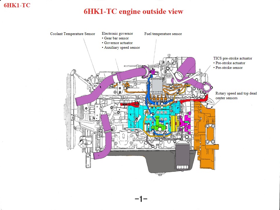
Isuzu 6HK1 မီးသတ်ကယ်ဆယ်ရေးယာဉ်များ , ဟုလည်း အမည်ပေးထားသော Isuzu မီးသတ်ကား , Isuzu မီးသတ်ကားအင်ဂျင် အပူလွန်ကဲပါက အောက်ပါနေရာများကို ဦးစွာစစ်ဆေးသင့်သည်။ ၁။ အအေးပေးစနစ်- ပန်ကာပျက်စီးခြင်း၊ ရေတိုင်ကီပိတ်ဆို့ခြင်း၊ သာမိုစတက်ပျက်စီးခြင်း သို့မဟုတ် အအေးခံရည်မလုံလောက်ခြင်းကဲ့သို့သော ပြဿနာများသည် အင်ဂျင်အပူလွန်ကဲခြင်းကို ဖြစ်စေနိုင်သည်။ ၂။ ဆီအရည်အသွေးနှင့် ပမာဏ- ဆီအရည်အသွေးညံ့ဖျင်းခြင်း သို့မဟုတ် ဆီမလုံလောက်ခြင်းကလည်း အင်ဂျင်အပူလွန်ကဲခြင်းကို ဖြစ်စေနိုင်သည်။ ၃။ ဆလင်ဒါပေါက်ခြင်း၊ ဆလင်ဒါလိုင်နာ အက်ကွဲခြင်း သို့မဟုတ် ဆလင်ဒါလိုင်နာ အက်ကွဲခြင်းကဲ့သို့သော စက်ပိုင်းဆိုင်ရာ ချို့ယွင်းမှုများသည်လည်း ဤဖြစ်စဉ်ကို ဖြစ်စေနိုင်သည်။ အကြီးစားဒီဇယ်အင်ဂျင်တစ်ခုအနေဖြင့် Isuzu 6HK1 အင်ဂျင်သည် ပြုပြင်ထိန်းသိမ်းမှုအတွက် နည်းပညာဆိုင်ရာသတ်မှတ်ချက်များကို တိကျစွာလိုက်နာရန် လိုအပ်ပါသည်။ အဓိကအချက်များမှာ အောက်ပါအတိုင်းဖြစ်သည်။ ၁။ ဖွဲ့စည်းပုံဆိုင်ရာ နားလည်မှု၊ ဖြုတ်တပ်ခြင်းနှင့် တပ်ဆင်ခြင်းဆိုင်ရာ သတ်မှတ်ချက်များ ကရန့်ရှပ်-ချိတ်ဆက်မှုရော့ ယန္တရား ဆလင်ဒါလိုင်နာသည် လျော့ရဲသောဒီဇိုင်းရှိပြီး ဖြုတ်တပ်ခြင်းနှင့် တပ်ဆင်ခြင်းပြုလုပ်စဉ်အတွင်း ပြုတ်ကျခြင်းမှ ကာကွယ်ရန် အထူးကိရိယာများ လိုအပ်ပါသည်။ စံသတ်မှတ်ထားသော အကွာအဝေးမှာ 0.122–0.156 မီလီမီတာ ဖြစ်သည်။ ပစ္စတင်အပြင်ဘက်အချင်းသည် တင်းကျပ်သောသည်းခံနိုင်စွမ်း (114.894–114.909 မီလီမီတာ) ရှိသည်။ တပ်ဆင်စဉ်အတွင်း ပစ္စတင်လက်စွပ်ဖွင့်သည့်ဦးတည်ချက်နှင့် "နေရာသုံးခု" (အဆုံးနေရာ၊ ဘေးနေရာနှင့် နောက်နေရာ) ချိန်ညှိမှုကို အာရုံစိုက်ပါ။ အောက်ပိုင်းကရန်ခန်းသည် တစ်ပိုင်းတည်းသောဖွဲ့စည်းပုံဖြစ်ပြီး ပုံပျက်ခြင်းမှကာကွယ်ရန် ပြုပြင်ထိန်းသိမ်းမှုကာလအတွင်း မတင်ရမည်။ အချိန်ကိုက်စနစ် ချိန်ညှိခြင်း ဂီယာဘောက်စ်တပ်ဆင်စဉ်အတွင်း ခရက်ရှပ်ဂီယာနှင့် idler ဂီယာအမှတ်အသားများကို ချိန်ညှိပါ။ camshaft B အမှတ်အသားသည် ဆလင်ဒါခေါင်းမျက်နှာပြင်နှင့် တစ်ပြေးညီဖြစ်ရမည်။ အင်ဂျင်သည် ပထမဆလင်ဒါရှိ ဖိသိပ်မှုအပေါ်ဆုံး dead center တွင် ရှိသင့်သည်။ လောင်စာထိုးပန့်တပ်ဆင်သည့်အခါ အချိန်ကိုက်ညွှန်ပြချက်ကို ချိတ်ဆက်ကိရိယာပေါ်ရှိ S အမှတ်နှင့် ချိန်ညှိပြီး ထိုးသွင်းမှုမြှင့်တင်ကိရိယာအမှတ်အသားကို ပန့်ကိုယ်ထည်ညွှန်ပြချက်နှင့် ချိန်ညှိပါ။ • linear DC မော်တာသည် ထိန်းချုပ်ယူနစ် အထွက်အချက်ပြမှုအောက်ရှိ ကွိုင်ကို အပေါ်အောက် တွန်းပေးသည်။ • ကွိုင်တပ်ဆင်မှုပေါ်တွင်တပ်ဆင်ထားသော ချိတ်ဆက်တံသည် ကွိုင်၏ အပေါ်အောက်ရွေ့လျားမှုကို ချိတ်ဆက်ဘလောက်သို့ ပေးပို့ပြီး ချိတ်ဆက်ဘလောက်ကို ရစ်ခ်၏အဆုံးတွင် တပ်ဆင်ထားသည်။ ချိတ်ဆက်ဘလောက်၏တွန်းအားအောက်တွင်၊ ထိုးသွင်းသောလောင်စာပမာဏကိုပြောင်းလဲရန် ရစ်ခ်သည် ဘယ်နှင့်ညာသို့ ရွေ့လျားသည်။ ကွိုင်တပ်ဆင်မှု အပေါ်သို့ရွေ့လျားသောအခါ၊ ချိတ်ဆက်မှုသည် ဆီ၏ဦးတည်ရာကိုတိုးမြှင့်ရန် ရစ်ခ်ကိုတွန်းသည်။ ပြောင်းပြန်အားဖြင့် ကွိုင်တပ်ဆင်မှု အောက်သို့ကျဆင်းသောအခါ၊ ရစ်ခ်သည် ဆီလျှော့ချသည့်ဦးတည်ရာသို့ ရွေ့လျားပြီး ကော်လံ၏လုပ်ဆောင်ချက်မှာ ဒေါင်လိုက်ရွေ့လျားမှုကို ရစ်ခ်၏အမြင့်သို့ပြောင်းလဲရန်ဖြစ်သည်။ • ကြေးနီဘလောက်ကို ချိတ်ဆက်ဘလောက်၏အပေါ်ပိုင်းတွင် rack sensor တစ်ခုဖွဲ့စည်းရန်တပ်ဆင်ထားသည်။ rack sensor သည် rack stroke ကို ထောက်လှမ်းပြီး ဤတန်ဖိုးကို control unit သို့ ပြန်လည်ပေးပို့သောကြောင့် rack stroke နှင့် target rack stroke နှစ်ခုကြား ကွာခြားချက်သည် သုညသို့ နီးကပ်လာသည်အထိ စဉ်ဆက်မပြတ် နှိုင်းယှဉ်နိုင်သည်။ ဤလုပ်ငန်းစဉ်သည် တိကျမှုနှင့် တုံ့ပြန်မှုကို ထိန်းချုပ်ရန် အလွန်အရေးကြီးပါသည်။ ၂။ အဓိကစနစ်ပြုပြင်ထိန်းသိမ်းမှုအချက်...
အသေးစိတ်
ဆက်လက်ဖတ်ရှုပါ၊ သတင်းအချက်အလက်များကို စောင့်မျှော်ပါ၊ စာရင်းသွင်းပါ နှင့် သင်၏အမြင်များကို ကျွန်ုပ်တို့အား ပြောပြရန် ကြိုဆိုပါသည်။

 IPv6 ကွန်ယက်ကိုထောက်ခံသည်

 မြန်မာ
 English
 français
 Deutsch
 русский
 italiano
 español
 português
 Nederlands
 العربية
 日本語
日本語 한국의
한국의 Türkçe
 Melayu
 ไทย
ไทย Tiếng Việt
 Indonesia
  中文
中文 қазақ
қазақ Filipino
 српски