မက်ဆေ့ခ်ျထားခဲ့ပါ
ကျွန်တော်တို့ရဲ့ထုတ်ကုန်တွေကို စိတ်ဝင်စားရင်နဲ့ အသေးစိတ်သိချင်ရင် ဒီမှာမက်ဆေ့ခ်ျထားခဲ့ပါ၊ ကျွန်တော်တို့က အမြန်ဆုံး ပြန်လည်ဖြေကြားပေးပါမယ်။

Isuzu မီးသတ်ကား 4HK1-TC အင်ဂျင်ပြုပြင်ထိန်းသိမ်းမှုလက်စွဲစာအုပ်၊ အင်ဂျင်ပြုပြင်ရေးလက်စွဲဟုလည်းခေါ်သည် Isuzu မီးသတ်ကား သို့မဟုတ် အင်ဂျင်နီယာစာအုပ် Isuzu မီးသတ်ယာဉ် ။
Isuzu မီးသတ်ကား 4HK1-TC အင်ဂျင်သည် မီးသတ်ကားများတွင် ကျယ်ကျယ်ပြန့်ပြန့်အသုံးပြုသည့် မြင့်မားသောစွမ်းဆောင်ရည်ရှိသော ဒီဇယ်အင်ဂျင်တစ်ခုဖြစ်ပြီး ၎င်း၏ယုံကြည်စိတ်ချရမှု၊ တာရှည်ခံမှုနှင့် မြင့်မားသောစွမ်းဆောင်ရည်တို့အတွက် လူသိများသည်။ အင်ဂျင်၏ ရေရှည်တည်ငြိမ်သောလည်ပတ်မှုကို သေချာစေရန်အတွက် ပုံမှန်ပြုပြင်ထိန်းသိမ်းမှုနှင့် ပြုပြင်မှုများသည် မရှိမဖြစ်လိုအပ်သည်။ ဤဆောင်းပါးသည် ပြုပြင်ထိန်းသိမ်းရေးဝန်ထမ်းများကို ပိုမိုကောင်းမွန်စွာ နားလည်ပြီး လည်ပတ်နိုင်စေရန်အတွက် Isuzu မီးသတ်ကား 4HK1-TC အင်ဂျင်ပြုပြင်ထိန်းသိမ်းမှုလက်စွဲစာအုပ်၏ အဓိကအကြောင်းအရာများကို အကျဉ်းချုပ်မိတ်ဆက်ပေးပါမည်။
၁။ အင်ဂျင်ခြုံငုံသုံးသပ်ချက်
4HK1-TC အင်ဂျင်သည် 5.2 လီတာ အရွယ်အစားရှိပြီး အမြင့်ဆုံးပါဝါ 190 မြင်းကောင်ရေရှိသော 4-cylinder inline turbocharged ဒီဇယ်အင်ဂျင်ဖြစ်သည်။ အင်ဂျင်သည် အဆင့်မြင့် common rail fuel injection စနစ်နှင့် electronic control unit (ECU) ကို အသုံးပြုထားသောကြောင့် လောင်စာဆီသုံးစွဲမှု ပိုမိုမြင့်မားပြီး ထုတ်လွှတ်မှု နည်းပါးသည်။
၂။ နေ့စဉ်ပြုပြင်ထိန်းသိမ်းမှု
နေ့စဉ်ပြုပြင်ထိန်းသိမ်းမှုသည် အင်ဂျင်ပုံမှန်လည်ပတ်မှုကိုသေချာစေရန် အခြေခံဖြစ်သည်။ ပြုပြင်ထိန်းသိမ်းမှုလက်စွဲတွင် ဆီနှင့်အအေးပေးအရည်အဆင့်စစ်ဆေးခြင်း၊ လေစစ်သန့်ရှင်းရေး သို့မဟုတ် အစားထိုးခြင်း၊ လောင်စာဆီစစ်အစားထိုးခြင်း စသည်တို့ အပါအဝင် နေ့စဉ်စစ်ဆေးရမည့်အချက်များကို အသေးစိတ်ဖော်ပြထားသည်။ ထို့အပြင်၊ လက်စွဲတွင် အင်ဂျင်ဆီနှင့် ဆီစစ်ကို ပုံမှန်လဲလှယ်ရန် အကြံပြုချက်များကိုလည်း ပေးထားပြီး ပုံမှန်အားဖြင့် ကီလိုမီတာ ၅၀၀၀ တစ်ကြိမ် သို့မဟုတ် ၆ လတစ်ကြိမ်ဖြစ်သည်။
၃။ ချို့ယွင်းချက်ရှာဖွေခြင်း
ပြုပြင်ထိန်းသိမ်းမှုလက်စွဲတွင် ပြုပြင်ထိန်းသိမ်းရေးဝန်ထမ်းများအား ပြဿနာများကို လျင်မြန်စွာရှာဖွေဖြေရှင်းနိုင်ရန် အသေးစိတ်ချို့ယွင်းချက်ရှာဖွေခြင်းလုပ်ငန်းစဉ်ပါရှိသည်။ လက်စွဲတွင် အဖြစ်များသောချို့ယွင်းချက်ကုဒ်များနှင့် ၎င်းတို့၏အဓိပ္ပာယ်များကို စာရင်းပြုစုထားပြီး သက်ဆိုင်ရာဖြေရှင်းနည်းများကို ပေးထားသည်။ ဥပမာအားဖြင့် အင်ဂျင်ပါဝါနည်းနေပါက လက်စွဲတွင် ပြုပြင်ထိန်းသိမ်းရေးဝန်ထမ်းများအား လောင်စာစနစ်၊ တာဘိုချာဂျာနှင့် အိတ်ဇောစနစ်စသည်တို့ကို စစ်ဆေးရန် လမ်းညွှန်ပေးမည်ဖြစ်သည်။
၄။ ပြုပြင်မွမ်းမံခြင်းနှင့် အစိတ်အပိုင်းများ အစားထိုးခြင်း
ပြုပြင်မွမ်းမံခြင်း သို့မဟုတ် အစိတ်အပိုင်းများ အစားထိုးရန် လိုအပ်သော အင်ဂျင်များအတွက် ပြုပြင်ထိန်းသိမ်းမှုလက်စွဲတွင် အသေးစိတ်အဆင့်များနှင့် ကြိုတင်ကာကွယ်မှုများကို ပေးထားသည်။ ဥပမာအားဖြင့်၊ ပစ္စတင်ကွင်းများ၊ အဆို့ရှင်လမ်းညွှန်များနှင့် ဝက်ဝံများကဲ့သို့သော အဓိကအစိတ်အပိုင်းများကို အစားထိုးသည့်အခါ၊ လက်စွဲတွင် ဖယ်ရှားခြင်းနှင့် တပ်ဆင်ခြင်းအဆင့်များအပြင် လိုအပ်သောကိရိယာများနှင့် torque သတ်မှတ်ချက်များကို အသေးစိတ်ဖော်ပြထားသည်။
၅။ ဘေးကင်းရေး ကြိုတင်ကာကွယ်မှုများ
ပြုပြင်ထိန်းသိမ်းမှုလက်စွဲစာအုပ်သည် ဘေးကင်းစွာလည်ပတ်ခြင်း၏ အရေးပါမှုကို အထူးအလေးပေးထားသည်။ ပြုပြင်ထိန်းသိမ်းမှုလုပ်ငန်းများ မလုပ်ဆောင်မီ အင်ဂျင်လုံးဝအေးသွားပြီး ပါဝါထောက်ပံ့မှုကို ဖြတ်တောက်ထားကြောင်း သေချာစေရမည်။ ထို့အပြင် လက်စွဲစာအုပ်တွင် လက်အိတ်၊ မျက်မှန်နှင့် အကာအကွယ်အဝတ်အစားကဲ့သို့သော ကိုယ်ရေးကိုယ်တာကာကွယ်ရေးပစ္စည်းများ အသုံးပြုရန် အကြံပြုချက်များလည်း ပါရှိသည်။
အပိုင်း ၁က
အင်ဂျင်ထိန်းချုပ်စနစ်
မာတိကာ
စာမျက်နှာ
[supportFields ဆိုရင်]> TOC \h \z \t "1A,1,1A-,2"
အင်ဂျင်ထိန်းချုပ်စနစ်
[supportFields ဆိုရင်]>
၄
[gte mso ၉ ဖြစ်ရင်]>
ကြိုတင်သတိပေးချက်များ
[supportFields ရှိရင်]>
၄
[gte mso ၉ ဖြစ်ရင်]>
လုပ်ဆောင်ချက်နှင့် အလုပ်လုပ်ပုံအခြေခံမူ
[supportFields ဆိုရင်]>
၅
[gte mso ၉ ဖြစ်ရင်]>
အစိတ်အပိုင်းများ ဖွဲ့စည်းပုံပုံ
[supportFields ဆိုရင်]>
၂၁
[gte mso ၉ ဖြစ်ရင်]>
ဆားကစ်ပုံ
[supportFields ဆိုရင်]>
၂၅
[gte mso ၉ ဖြစ်ရင်]>
အမှားကို ဘယ်လိုရှာဖွေမလဲ
[supportFields ဆိုရင်]>
၄၂
[gte mso ၉ ဖြစ်ရင်]>
ချို့ယွင်းချက်ရှာဖွေမီတာမှတစ်ဆင့် ချို့ယွင်းချက်ရှာဖွေခြင်းလုပ်ငန်းစဉ်များ
[supportFields ဆိုရင်]>
၄၈
[gte mso ၉ ဖြစ်ရင်]>
လုပ်ဆောင်ချက်စစ်ဆေးမှုခြုံငုံသုံးသပ်ချက်
[supportFields ဆိုရင်]>
၅၀
[gte mso ၉ ဖြစ်ရင်]>
စုံစမ်းမေးမြန်းခြင်း
[supportFields ဆိုရင်]>
၅၁
[gte mso ၉ ဖြစ်ရင်]>
အင်ဂျင်ထိန်းချုပ်စနစ်စစ်ဆေးခြင်း
[supportFields ဆိုရင်]>
၅၃
[gte mso ၉ ဖြစ်ရင်]>
ချို့ယွင်းချက်ရှာဖွေခြင်းမီတာဒေတာစာရင်း
[supportFields ဆိုရင်]>
၅၅
[gte mso ၉ ဖြစ်ရင်]>
ချို့ယွင်းချက်ရှာဖွေမီတာဒေတာစာရင်းအကြောင်းအရာများ
[supportFields ဆိုရင်]>
၅၈
[gte mso ၉ ဖြစ်ရင်]>
ချို့ယွင်းချက်ရှာဖွေစစ်ဆေးသည့် မီတာ အထွက်
[supportFields ဆိုရင်]>
၆၄
[gte mso ၉ ဖြစ်ရင်]>
ချို့ယွင်းချက်ရှာဖွေမီတာစတင်မှုပျက်ကွက်ခြင်း
[supportFields ဆိုရင်]>
၆၅
[gte mso ၉ ဖြစ်ရင်]>
ချို့ယွင်းချက်ရှာဖွေမီတာ ဆက်သွယ်ရေးချို့ယွင်းမှု (ကိုးကားချက်)
[supportFields ဆိုရင်]>
၆၇
[gte mso ၉ ဖြစ်ရင်]>
ECM နှင့် ဆက်သွယ်မှု ချို့ယွင်းမှု (ကိုးကားချက်)
[supportFields ဆိုရင်]>
၇၁
[gte mso ၉ ဖြစ်ရင်]>
စနစ်စတင်ခြင်း အတည်ပြုချက်
[supportFields ဆိုရင်]>
၇၄
[gte mso ၉ ဖြစ်ရင်]>
အင်ဂျင် MIL အလင်းရောင်ပေးသည့် လျှပ်စစ်ပတ်လမ်းစနစ် အတည်ပြုချက်
[supportFields ဆိုရင်]>
၇၇
[gte mso ၉ ဖြစ်ရင်]>
အင်ဂျင် MIL မှိတ်တုတ်မှိတ်တုတ်ဖြစ်နေသော လျှပ်စစ်ပတ်လမ်းစနစ် အတည်ပြုချက်
[supportFields ဆိုရင်]>
၇၈
[gte mso ၉ ဖြစ်ရင်]>
အိတ်ဇောဓာတ်ငွေ့ပြန်လည်လည်ပတ်မှု (EGR) ထိန်းချုပ်စနစ်စစ်ဆေးခြင်း
[supportFields ဆိုရင်]>
၈၀
[gte mso ၉ ဖြစ်ရင်]>
အပူပေးစနစ် ထိန်းချုပ်စစ်ဆေးခြင်း
[supportFields ရှိရင်]>
၈၄
[gte mso ၉ ဖြစ်ရင်]>
အိတ်ဇောဘရိတ်/လေဝင်ပေါက် ကန့်သတ်ချက် ထိန်းချုပ်စနစ် စစ်ဆေးခြင်း
[supportFields ဆိုရင်]>
၈၇
[gte mso ၉ ဖြစ်ရင်]>
ရောဂါရှာဖွေရေးပြဿနာကုဒ် (DTC) ခြုံငုံသုံးသပ်ချက်
[supportFields ဆိုရင်]>
၉၂
[gte mso ၉ ဖြစ်ရင်]>
DTC P0016 (ဖလက်ရှ်ကုဒ် ၁၆)
[supportFields ဆိုရင်]>
၉၅
[gte mso ၉ ဖြစ်ရင်]>
DTC P0087 (ဖလက်ရှ်ကုဒ် ၂၂၅)
[supportFields ဆိုရင်]>
၉၇
[gte mso ၉ ဖြစ်ရင်]>
DTC P0088 (ဖလက်ရှ်ကုဒ် ၁၁၈)
[supportFields ဆိုရင်]>
၁၀၃
[gte mso ၉ ဖြစ်ရင်]>
DTC P0089 (ဖလက်ရှ်ကုဒ် ၁၅၁)
[supportFields ရှိရင်]>
၁၀၉
[gte mso ၉ ဖြစ်ရင်]>
DTC P0091၊ P0092 (ဖလက်ရှ်ကုဒ် ၂၄၇)
[supportFields ဆိုရင်]>
၁၁၂
[gte mso ၉ ဖြစ်ရင်]>
DTC P0093 (ဖလက်ရှ်ကုဒ် ၂၂၇)
[supportFields ဆိုရင်]>
၁၁၆
[gte mso ၉ ဖြစ်ရင်]>
DTC P0107၊ P0108 (ဖလက်ရှ်ကုဒ် ၃၂)
[supportFields ဆိုရင်]>
၁၂၂
[gte mso ၉ ဖြစ်ရင်]>
DTC P0112၊ P0113 (ဖလက်ရှ်ကုဒ် ၂၂)
[supportFields ရှိရင်]>
၁၂၇
[gte mso ၉ ဖြစ်ရင်]>
DTC P0117၊ P0118 (ဖလက်ရှ်ကုဒ် ၂၃)
[supportFields ဆိုရင်]>
၁၃၂
[gte mso ၉ ဖြစ်ရင်]>
DTC P0122၊ P0123 (ဖလက်ရှ်ကုဒ် ၄၃)
[supportFields ဆိုရင်]>
၁၃၇
[gte mso ၉ ဖြစ်ရင်]>
DTC P0182၊ P0183 (ဖလက်ရှ်ကုဒ် ၂၁၁)
[supportFields ဆိုရင်]>
၁၄၂
[gte mso ၉ ဖြစ်ရင်]>
DTC P0192၊ P0193 (ဖလက်ရှ်ကုဒ် ၂၄၅)
[supportFields ရှိရင်]>
၁၄၇
[gte mso ၉ ဖြစ်ရင်]>
[supportFields ဆိုရင်]> DTC P0201, P0202, P0203, P0204 (ဖလက်ရှ်ကုဒ် ၂၇၁,၂၇၂,၂၇၃,၂၇၄).................................................. 1A-157
DTC P0217 (ဖလက်ရှ်ကုဒ် 542)........................................................................................................ 1A-170
DTC P0219 (ဖလက်ရှ်ကုဒ် 543)........................................................................................................ 1A-172
DTC P0234 (ဖလက်ရှ်ကုဒ် ၄၂)။........................................................................................................ 1A-175
DTC P0299 (ဖလက်ရှ်ကုဒ် ၆၅)........................................................................................................ 1A-178
DTC P0335 (ဖလက်ရှ်ကုဒ် ၁၅)........................................................................................................ 1A-182
DTC P0336 (ဖလက်ရှ်ကုဒ် ၁၅)........................................................................................................ 1A-187
DTC P0340 (ဖလက်ရှ်ကုဒ် ၁၄)........................................................................................................ 1A-190
DTC P0341 (ဖလက်ရှ်ကုဒ် ၁၄)........................................................................................................ 1A-195
DTC P0380 (ဖလက်ရှ်ကုဒ် ၆၆)........................................................................................................ 1A-198
DTC P0381 (ဖလက်ရှ်ကုဒ် ၆၇)........................................................................................................ 1A-201
DTC P0404 (ဖလက်ရှ်ကုဒ် ၄၅)........................................................................................................ 1A-205
DTC P0409 (ဖလက်ရှ်ကုဒ် ၄၄)........................................................................................................ 1A-208
DTC P0477, P0478 (ဖလက်ရှ်ကုဒ် ၄၆)................................................................................................ 1A-212
DTC P0500 (ဖလက်ရှ်ကုဒ် ၂၅)........................................................................................................ 1A-216
DTC P0502, P0503 (ဖလက်ရှ်ကုဒ် ၂၅)................................................................................................ 1A-218
DTC P0563 (ဖလက်ရှ်ကုဒ် ၃၅)........................................................................................................ 1A-223
DTC P0601 (ဖလက်ရှ်ကုဒ် ၅၃)။........................................................................................................ 1A-225
DTC P0602 (ဖလက်ရှ်ကုဒ် ၁၅၄)........................................................................................................ 1A-226
DTC P0604၊ P0606၊ P060B (ဖလက်ရှ်ကုဒ်များ ၁၅၃၊ ၅၁၊ ၃၆).................................................................. 1A-228
DTC P0641 (ဖလက်ရှ်ကုဒ် ၅၅)........................................................................................................ 1A-230
DTC P0650 (ဖလက်ရှ်ကုဒ် ၇၇)။........................................................................................................ 1A-233
DTC P0651 (ဖလက်ရှ်ကုဒ် ၅၆)........................................................................................................ 1A-237
DTC P0685, P0687 (ဖလက်ရှ်ကုဒ် ၄၁၆)................................................................................................ 1A-241
DTC P0697 (ဖလက်ရှ်ကုဒ် ၅၇)။........................................................................................................ 1A-245
DTC P1093 (ဖလက်ရှ်ကုဒ် ၂၂၇)........................................................................................................ 1A-248
DTC P1261, P1262 (ဖလက်ရှ်ကုဒ် ၃၄)................................................................................................ 1A-253
DTC P1404 (ဖလက်ရှ်ကုဒ် ၄၅)........................................................................................................ 1A-255
DTC P1621 (ဖလက်ရှ်ကုဒ် ၅၄)........................................................................................................ 1A-257
DTC P2122, P2123 (ဖလက်ရှ်ကုဒ် 121)........................................................................................ 1A-258
DTC P2127, P2128 (ဖလက်ရှ်ကုဒ် 122)........................................................................................ 1A-264
DTC P2138 (ဖလက်ရှ်ကုဒ် ၁၂၄)................................................................................................ 1A-270
DTC P2146, P2149 (ဖလက်ရှ်ကုဒ် ၁၅၈)................................................................................................ 1A-273
DTC P2228, P2229 (ဖလက်ရှ်ကုဒ် ၇၁)................................................................................................ 1A-279
DTC P253A (ဖလက်ရှ်ကုဒ် ၂၈)........................................................................................................ 1A-284
DTC P256A (ဖလက်ရှ်ကုဒ် ၃၁)........................................................................................................ 1A-287
DTC U0073 (ဖလက်ရှ်ကုဒ် ၈၄)........................................................................................................ 1A-291
ရောဂါလက္ခဏာရှာဖွေခြင်း................................................................................................................... 1A-296
ဖြစ်စဉ်- Intermittence ......................................................................................................... 1A-297
ရောဂါလက္ခဏာ: စက်နှိုးရခက်ခဲခြင်း........................................................................................................ 1A-300
ဖြစ်စဉ်- အရှိန်မြင့်တက်ခြင်း၊ မတည်ငြိမ်သော idling သို့မဟုတ် အင်ဂျင်ရပ်တန့်ခြင်း........................................................................ 1A-303
ဖြစ်စဉ်- မြင့်မားသော idling speed.................................................................................................. 1A-306
လက္ခဏာ: အရေးပေါ်ရပ်တန့်ခြင်း........................................................................................................ 1A-307
လက္ခဏာ: အရေးပေါ်ပြောင်းလဲမှု................................................................................................................. 1A-309
ရောဂါလက္ခဏာ: ပါဝါမရှိခြင်း၊ အရှိန်မြှင့်ခြင်း မအောင်မြင်ခြင်း သို့မဟုတ် တုံ့ပြန်မှု နှောင့်နှေးခြင်း................................................................. 1A-311
ဖြစ်စဉ်- ခေတ္တရပ်တန့်လည်ပတ်မှု၊ အရှိန်မြှင့်မှုပျက်ကွက်မှု........................................................................ 1A-314
ရောဂါလက္ခဏာ: လောင်ကျွမ်းသံ........................................................................................................ 1A-316
လက္ခဏာ: လောင်စာဆီ ချွေတာရေး ထိရောက်မှု နိမ့်ကျသည်.................................................................................. 1A-317
ဖြစ်ရပ်- အိတ်ဇောဓာတ်ငွေ့မှ မီးခိုးမည်းများ................................................................................. 1A-319
လက္ခဏာ: အိတ်ဇောဓာတ်ငွေ့မှ အဖြူရောင်မီးခိုးများထွက်ခြင်း.................................................................................. 1A-321
အဓိက အာရုံခံကိရိယာ ကန့်သတ်ချက်များ................................................................................................................. 1A-323
အထူးကိရိယာများ................................................................................................................................. 1A-325
အစီအစဉ် ................................................................................................................................................ 1A-326
ပရိုဂရမ်းမင်း စည်းမျဉ်း........................................................................................................................ ၁က-၃၂၆
အစီအစဉ် ................................................................................................................................................ 1A-326
ထိုးသွင်းစုပ်စက် သင်ယူခြင်း................................................................................................................. 1A-328
ချိန်ညှိမှု................................................................................................................................. 1A-328
ဆားကစ်စမ်းသပ်ကိရိယာများအသုံးပြုခြင်း
ရောဂါရှာဖွေရေးပရိုဂရမ်အရ ရောဂါရှာဖွေရာတွင်၊ အခြားနည်းဖြင့် သတ်မှတ်ထားခြင်းမရှိပါက ပါဝါထရိန်လျှပ်စစ်စနစ်ရောဂါရှာဖွေမှုအတွက် စမ်းသပ်မီးအိမ်ကို မသုံးပါနှင့်။ ရောဂါရှာဖွေရေးပရိုဂရမ်အတွက် probe terminal ကို အသုံးပြုမည်ဆိုပါက terminal testing adapter kit 5-8840-2835-0 ကို အသုံးပြုပါ။
ဈေးကွက်တွင်ရရှိနိုင်သော လျှပ်စစ်ပစ္စည်း
ဈေးကွက်တွင်ရရှိနိုင်သော လျှပ်စစ်အစိတ်အပိုင်းများဆိုသည်မှာ ယာဉ်တွင်တပ်ဆင်ရန် ဈေးကွက်မှဝယ်ယူသော လျှပ်စစ်အစိတ်အပိုင်းများကို ဆိုလိုသည်။ ယာဉ်ဒီဇိုင်းအဆင့်တွင် ဤအစိတ်အပိုင်းများကို ထည့်သွင်းစဉ်းစားခြင်းမရှိသောကြောင့် ဤအစိတ်အပိုင်းများကိုအသုံးပြုသည့်အခါ ၎င်းတို့ကို အာရုံစိုက်ပါ။
သတိပြုရန်:
ဈေးကွက်တွင်ရရှိနိုင်သော လျှပ်စစ်အစိတ်အပိုင်း ပါဝါနှင့် မြေပြင်ကို လျှပ်စစ်ထိန်းချုပ်စနစ် ပတ်လမ်းနှင့် မသက်ဆိုင်ဘဲ ပတ်လမ်းနှင့် ချိတ်ဆက်ထားရမည်။
ဈေးကွက်တွင်ရရှိနိုင်သော လျှပ်စစ်အစိတ်အပိုင်းများကို အသုံးပြုနိုင်သော်လည်း ၎င်းတို့သည် အချို့ကိစ္စများတွင် လျှပ်စစ်ထိန်းချုပ်စနစ်၏ လုပ်ဆောင်နိုင်စွမ်းဆိုင်ရာ ချို့ယွင်းချက်ကို ဖြစ်စေနိုင်သည်။ ၎င်းတွင် မိုဘိုင်းတယ်လီဖုန်း၊ ရေဒီယိုကဲ့သို့သော လျှပ်စစ်စနစ်နှင့် မချိတ်ဆက်ထားသော ကိရိယာများ ပါဝင်သည်။ ထို့ကြောင့် ပါဝါထရိန်းရောဂါရှာဖွေမှုတွင် ဈေးကွက်တွင်ရရှိနိုင်သော လျှပ်စစ်အစိတ်အပိုင်းများ တပ်ဆင်ထားခြင်းရှိမရှိ ဦးစွာစစ်ဆေးပါ။ ထိုသို့ဖြစ်ပါက ၎င်းတို့ကို ယာဉ်မှဖယ်ရှားပါ။ အစိတ်အပိုင်းဖယ်ရှားပြီးနောက်တွင် အမှားရှိနေသေးပါက ရောဂါရှာဖွေရန်အတွက် အထွေထွေလုပ်ငန်းစဉ်ကို လိုက်နာပါ။
ESD ကြောင့် ပျက်စီးမှု
လျှပ်စစ်ထိန်းချုပ်စနစ်ရှိ အီလက်ထရွန်းနစ်အစိတ်အပိုင်းများသည် အလွန်နိမ့်သောဗို့အားအောက်တွင် အလုပ်လုပ်နိုင်သောကြောင့် ESD ကြောင့် ပျက်စီးလွယ်ပါသည်။ အချို့သော အီလက်ထရွန်းနစ်အစိတ်အပိုင်းများသည် လူသားများ မသိရှိနိုင်သော 100V အောက်ရှိ static electricity ကြောင့် ပျက်စီးသွားမည်ဖြစ်သည်။ လူသားများ သိရှိနိုင်သော ESD သည် 4000V ဗို့အား လိုအပ်သည်။ ကိစ္စအများစုတွင် လူသားသည် static electricity ကို သယ်ဆောင်မည်ဖြစ်ပြီး ပွတ်တိုက်မှုနှင့် induction electrification သည် အဖြစ်အများဆုံးဖြစ်သည်။
● လူသားသည် ထိုင်ခုံပေါ်တွင် ဘေးတစ်ဖက်တစ်ချက် ရွေ့လျားသောအခါ၊ ၎င်းသည် ပွတ်တိုက်အားလျှပ်စစ်ဓာတ်အားကို ဖြစ်ပေါ်စေပါသည်။
● လျှပ်စစ်စီးဖိနပ်စီးထားသော လူတစ်ဦးသည် လျှပ်စစ်ဓာတ်အား မြင့်မားစွာ စီးဆင်းနေသော အရာဝတ္ထုအနီးတွင် ရှိနေသည့်အခါ၊ လူတစ်ဦး မြေပြင်ကို ထိလိုက်သည့်အချိန်တွင် လျှပ်စစ်စီးကူးမှု ဖြစ်ပေါ်မည်ဖြစ်သည်။ တူညီသော ပေါ်လစီရှိ အားသွင်းပစ္စည်းများသည် ဆန့်ကျင်ဘက် ပေါ်လစီရှိ အားသွင်းပစ္စည်းများနှင့် ထိတွေ့သောအခါတွင် လူတစ်ဦးသည် လျှပ်စစ်စီးကူးသွားမည်ဖြစ်သည်။ လျှပ်စစ်ဓာတ်သည် ပျက်စီးမှုကို ဖြစ်စေနိုင်သောကြောင့် အီလက်ထရွန်းနစ် အစိတ်အပိုင်းများကို ဂရုတစိုက် ကိုင်တွယ်ပြီး စမ်းသပ်ပါ။
သတိပြုရန်:
ESD ကြောင့် ပျက်စီးမှုကို ကာကွယ်ရန် အောက်ပါစည်းမျဉ်းများကို လိုက်နာပါ။
● ECM ဆားကစ်နောက်ကျောပြားနှင့် ဂဟေဆက်ထားသော ECM တာမီနယ် အဆက်အသွယ်တံများနှင့် အီလက်ထရွန်းနစ် အစိတ်အပိုင်းများကို မထိပါနှင့်။
● အစိတ်အပိုင်းတပ်ဆင်ခြင်းပြင်ဆင်မှုမပြီးမချင်း ပန်းခြံများကို အဖုံးမဖွင့်ပါနှင့်။
● အစိတ်အပိုင်းများကို အထုပ်ထဲမှ မထုတ်ယူမီ အထုပ်နှင့် ယာဉ်၏ ပုံမှန်မြေပြင်ကို ချိတ်ဆက်ပါ။
● ထိုင်ခုံပေါ်တွင် ဘေးတစ်ဖက်တစ်ချက် ရွေ့လျားနေပါက၊ သို့မဟုတ် ရပ်နေရာမှ ထိုင်နေပါက သို့မဟုတ် အကွာအဝေးတစ်ခုအတွင်း ရွေ့လျားနေစဉ် အစိတ်အပိုင်းကို လည်ပတ်နေပါက၊ အစိတ်အပိုင်းကို မတပ်ဆင်မီ ပုံမှန်မြေပြင်ကို ထိနေကြောင်း သေချာပါစေ။
လုပ်ဆောင်ချက်နှင့် အလုပ်လုပ်ပုံအခြေခံမူ
အင်ဂျင်ထိန်းချုပ်စနစ် (common rail)
စနစ်ခြုံငုံသုံးသပ်ချက်နှင့် အသေးစိတ်အချက်အလက်များ
အင်ဂျင်ထိန်းချုပ်စနစ် ဆိုသည်မှာ မောင်းနှင်မှုအခြေအနေအလိုက် အင်ဂျင်ကို အကောင်းဆုံးလောင်ကျွမ်းမှုအခြေအနေသို့ ထိန်းချုပ်ပေးသည့် လျှပ်စစ်ထိန်းချုပ်စနစ်ဖြစ်သည်။ ၎င်းတွင် အောက်ပါအစိတ်အပိုင်းများ ပါဝင်သည်-
● အီလက်ထရွန်းနစ်နည်းဖြင့် ထိန်းချုပ်ထားသော လောင်စာထိုးစနစ် (common rail အမျိုးအစား)
● EGR
ထို့အပြင်၊ အင်ဂျင်ထိန်းချုပ်စနစ်တွင် အောက်ပါစနစ်ထိန်းချုပ်မှုလုပ်ဆောင်ချက်များ ပါဝင်သည်။
● နွေးထွေးမှု ထိန်းချုပ်စနစ်
● အင်ဂျင်လည်ပတ်မှု အထွက်
● ဆက်သွယ်ရေးနှင့် ကိုယ်တိုင်ရောဂါရှာဖွေခြင်းလုပ်ဆောင်ချက်
[အဆုံး]
[if gte vml 1]>
အီလက်ထရွန်းနစ်နည်းဖြင့် ထိန်းချုပ်ထားသော လောင်စာထိုးစနစ် (common rail အမျိုးအစား)
common rail စနစ်ကို ဖိအားခန်းနှင့် injector ပါရှိသည်။ ဖိအားခန်းကို ဖိအားပေးထားသောလောင်စာဆီသိုလှောင်ရန် ဒီဇိုင်းထုတ်ထားပြီး common rail ဟုခေါ်သည်။ injector တွင် ဖိအားပေးထားသောလောင်စာဆီများကို လောင်ကျွမ်းခန်းသို့ ထိုးသွင်းရန် electronic control solenoid valve ပါရှိသည်။ injection control (injection pressure, injection rate နှင့် injection time) ကို ECM မှ ထိန်းချုပ်ထားသောကြောင့် common rail စနစ်သည် အင်ဂျင်အမြန်နှုန်းနှင့် ဝန်အားကို လွတ်လပ်စွာ ထိန်းချုပ်နိုင်သည်။ အင်ဂျင်အမြန်နှုန်းနည်းနေသော်လည်း တည်ငြိမ်သော injection pressure ကို ထိန်းသိမ်းထားနိုင်ပြီး ဒီဇယ်အင်ဂျင်စတင်လည်ပတ်ချိန်နှင့် အရှိန်မြှင့်ချိန်တွင် မီးခိုးမည်းမည်းထွက်မှုကို သိသိသာသာ လျှော့ချပေးမည်ဖြစ်သည်။ ဤထိန်းချုပ်မှုမှတစ်ဆင့် exhaust gas သည် သန့်ရှင်းလာပြီး exhaust volume လျော့နည်းလာပြီး output မြင့်မားလာမည်ဖြစ်သည်။
ထိုးသွင်းမှုပမာဏထိန်းချုပ်မှု
၎င်းသည် အင်ဂျင်အမြန်နှုန်းနှင့် အရှိန်မြှင့်နင်းဖွင့်ခြင်းမှ ရရှိသော အချက်ပြမှုအရ injector winding ကို ထိန်းချုပ်ပြီး ရလဒ်အနေဖြင့် အကောင်းဆုံးပမာဏရရှိရန် လောင်စာထိုးသွင်းမှုပမာဏကို ထိန်းချုပ်ပေးသည်။
ထိုးသွင်းဖိအားထိန်းချုပ်မှု
အင်ဂျင်အမြန်နှုန်းနည်းနေသော်လည်း မြင့်မားသောဖိအားဖြင့် ထိုးသွင်းနိုင်စေရန်အတွက် common rail အတွင်းရှိ လောင်စာဖိအားကို ထိန်းချုပ်သင့်သည်။ အင်ဂျင်အမြန်နှုန်းနှင့် လောင်စာထိုးသွင်းမှုပမာဏအလိုက် common rail တွင် သင့်လျော်သောဖိအားကို တွက်ချက်ပြီး ထိန်းချုပ်ထိုးသွင်းပန့်မှတစ်ဆင့် သင့်လျော်သောလောင်စာပမာဏကို ထုတ်လွှတ်ကာ ဖိအားအောက်ရှိ common rail သို့ ပေးပို့ပါ။
ထိုးသွင်းချိန်ထိန်းချုပ်မှု
၎င်းသည် အချိန်ကိုက်လုပ်ဆောင်ချက်ကို အစားထိုးပြီး အင်ဂျင်အမြန်နှုန်းနှင့် ထိုးသွင်းမှုပမာဏအလိုက် သင့်လျော်သော လောင်စာထိုးသွင်းချိန်ကို လုပ်ဆောင်ပြီးနောက် ထိုးသွင်းကိရိယာကို ထိန်းချုပ်သည်။
ထိုးသွင်းမှုနှုန်း ထိန်းချုပ်ခြင်း
ဆလင်ဒါ၏လောင်ကျွမ်းမှုထိရောက်မှုကိုမြှင့်တင်ရန်အတွက်၊ မီးညှိရန်အတွက်လောင်စာအနည်းငယ်ထိုးသွင်းပါ (ထိုးသွင်းခြင်းမပြုမီ)။ မီးညှိပြီးနောက် ဒုတိယအကြိမ်ထိုးသွင်းခြင်း (အဓိကထိုးသွင်းခြင်း) ကိုလုပ်ဆောင်ပါ။ ထိုးသွင်းချိန်နှင့်ထိုးသွင်းပမာဏကို ထိုးသွင်းကိရိယာ (ထိုးသွင်းကိရိယာကွိုင်) မှတစ်ဆင့် ထိန်းချုပ်ပါ။
 [endif]
Fuel System
The common rail system consists of 2 fuel pressure systems.
● Low pressure inlet line: between the fuel tank and injection pump
● High pressure line: between the injection pump and injector
The fuel is sucked into injection pump from the fuel tank and boosted in the pump to supply to the common rail. At this point, the signal from ECM controls the suction control valve (the common rail pressure regulator) to control the fuel volume supplied to the common rail.
Fuel system diagram
[if gte vml 1]>
|
Key 1. Common Rail 2. Pressure limiting valve 3. Injector return pipe 4. Injector 5. Fuel return pipe 6. Fuel supply pipe |
7. Fuel tank 8. Breather valve 9. Starter pump 10. Fuel filter (with oil-water separator) 11. Return valve 12. Fuel injection pump |
EGR (Exhaust gas recirculation)
Egr system recycles a part of exhaust gas to the intake manifold and consequently reduces the nitrogen oxides (NOx) emission. Through the EGR system, the driving operability and exhaust gas emission reduction can be achieved. The control current from the EGR controls the solenoid valve to work and consequently control the EGR valve lift. In addition, this system detects the actual valve lift with the EGR position sensor to realize the fine control over the EGR.
EGR will start working when the engine speed, engine coolant temperature, intake temperature and barometric pressure conditions are met. Then it will work out the valve opening according to the engine speed and target fuel injection volume. Basing on the calculated valve opening, it decides the solenoid valve drive load and then drives the valve. The air intake throttle will be shut down during EGR operation to enable the intake manifold inside pressure to reach the target value.
[if gte vml 1]>
[endif]
[if !mso]
|
[endif]
[if !mso]
|
[endif]
[if !mso]
|
[endif]
[if !mso]
|
|
Key 1. ECM 2. EGR position sensor 3. EGR valve 4. EGR cooler |
5. Intake throttle valve
|
Warming-up control
Warming-up control system
The warming-up control system is designed to ease the engine start at low temperature and reduce the white smoke and noise. With the starter switch active, ECM detects the engine coolant temperature according to the signal from the engine coolant temperature (ECT) sensor to adjust the warming-up time and achieve the appropriate starting conditions for the engine. In addition, the residual heat of warming-up can maintain the idling stable. ECM decides the warming-up time according to the engine coolant temperature to drive the warming-up relay and indicator lamp to work.
[endif]
[if gte vml 1]>
Overview of exhaust brake control
The exhaust brake exhaust pipe is provided with valve inside. Closing the valve can increase the exhaust stroke resistance and enhance the engine brake effect. The exhaust brake valve works according to the vacuum pressure. The exhaust brake vacuum pressure is controlled by the open and close of solenoid valve. ECM will enable the solenoid valve if the engine speed is above 575rpm and all the exhaust brake operating conditions are met.
Exhaust brake operating conditions
● Exhaust brake switch on
● Accelerator pedal not depressed
● Not detecting accelerator pedal position (APP) sensor abnormal, exhaust brake circuit abnormal, clutch switch abnormal, APP sensor switch abnormal, A/D switch abnormal etc.
● Clutch pedal not depressed
● System voltage above 24V
● Vehicle speed exceeding specified range
ECM
Overview of ECM
[if gte vml 1]>
ECM monitors the information from every sensor all the time to control the power train. ECM performs system diagnostic function to detect the system operation problem, remind the driver through the engine MIL and record DTC at the same time. DTC identifies the trouble zone to help the maintenance man.
ECM functions
ECM exports 5V voltage to power various sensors and switches. However, since the power is supplied by the ECM resistance, the test lamp connected to the circuit will not be on even if the resistance is very high. In some case, the common voltmeter cannot display the correct reading since its resistance is too low. To display the correct reading, ensure to use the digital multimeter of 10MΩ input impedance at least (5-8840-2691-0). ECM controls the ground circuit or power circuit through the transistor or other unit and consequently controls the output circuit.
ECM and composition parts
ECM can achieve the high steerability and fuel efficiency while maintaining the specified waste gas exhaust. ECM monitors the engine and vehicle performance through the crankshaft position (CKP) sensor and vehicle speed sensor (VSS) etc.
ECM voltage description
ECM applies the standard voltage to each switch and sensor. This is because the ECM resistance is very high while the voltage applied to the circuit is low. The test lamp will not illuminate even if connected in the circuit. Since the input impedance of voltmeter generally used by the maintenance man is very low, sometimes the voltmeter cannot display the correct reading. In such a case, use digital multimeter of 10MΩ input impedance (5- 8840 -2691-0) to get the correct voltage reading.
The ECM input/output unit is equipped with analog-digital converter, signal damping, counter and special actuator. ECM can control most composition parts through the electronic switch.
EEPROM
EEPROM is permanent storage chip soldered to the ECM back plate. To control the power train, ECM transmits the necessary program and calibration message to EEPROM.
Different from ROM, EEPROM cannot be replaced. If EEPROM is detected abnormal, replace the ECM directly.
Considerations for ECM repair
ECM can withstand the general current relevant to vehicle driving. Do not allow the circuit overload. During the open circuit and short circuit test, do not connect the ECM circuit to the ground wire or apply the voltage unless otherwise specified. For such circuit tests, ensure to use the digital multimeter (5-8840-2691-0).
 [endif]
The injection pump is the core part of common rail electronic fuel injection system. The injection pump is installed to the engine front. The common rail pressure regulator and fuel temperature (FT) sensor are the composition parts of the injection pump.
The fuel is fed to the injection pump from the fuel tank through the inside supply pump (rotor type). The supply pump feeds the fuel into 2 plunger compartments in the injection pump. The fuel fed to the plunger compartment is regulated by the common rail pressure regulator. The common rail pressure regulator is only controlled by the ECM supply current. The fuel flow will reach the maximum if no current is fed to the solenoid valve. Contrarily, the fuel will stop flowing when the solenoid valve current reaches the maximum. As the engine rotates, the two plungers build high pressure in the common rail. It controls the common rail pressure regulator according to the ECM signal and consequently controls the fuel volume and pressure to the common rail. In this way, the optimal operating state can be realized to enhance the fuel economical efficiency and reduce the NOx emission.
[if gte vml 1]>
Key
1. Fuel temperature (FT) sensor
2. Suction control valve (common rail pressure regulator)
Suction control valve (common rail pressure regulator)
ECM controls the load factor of common rail pressure regulator (the power-on time of common rail pressure regulator) to regulate the fuel volume fed to the high pressure plunger. To achieve the desired rail pressure, feed the proper amount of fuel to reduce the drive load of the injection pump. When the current is fed to the common rail pressure regulator, the variable electromotive force corresponding to the load factor will be generated to vary the fuel line opening and consequently adjust the fuel volume. When the common rail pressure regulator is switched off, the retracting spring will retract, the fuel line will completely open and the fuel will flow to the plunger (the maximum intake and maximum discharge). With the common rail pressure regulator open, the fuel line will close (normally open) under the function of the retracting spring. Through the open and close of common rail pressure regulator, the fuel corresponding to the working load rate will be supplied and then discharged from the plunger.
Fuel temperature (FT) sensor
FT sensor is installed to the injection pump and the thermistor changes the resistance along with the temperature variation. The resistance will be low if the fuel temperature is high and high if the fuel temperature is low. ECM applies 5V voltage to FT sensor through the load resistor and works out the fuel temperature according to the voltage variation to control the injection pump. The voltage will be low if the resistance is low (the temperature is high) and high if the resistance is high (the temperature is low).
Common rail
[if gte vml 1]>
Key
1. Pressure limiting valve
2. Common rail pressure sensor
Due to the common rail type electrical control fuel injection system, the common rail is provided between the injection pump and injector to store the high pressure fuel. The pressure sensor and pressure limiting valve are installed on the common rail. The pressure sensor detects the fuel pressure in the common rail and transmits the signal to ECM. Basing on this signal, ECM controls the fuel pressure in the common rail with the injection pump common rail pressure regulator. If the common rail inside fuel pressure is too high, the pressure limiting valve will open to release the pressure.
Common rail pressure sensor
The common rail pressure sensor is installed to the common rail to detect the fuel pressure in the rail and convert the pressure into voltage signal. The higher the pressure, the higher the voltage; the lower the pressure, the lower the voltage. ECM works out the actual common rail pressure (the fuel pressure) according to the voltage signal from the sensor to control the fuel injection.
Pressure limiting valve
[if gte vml 1]>
Key
1. Valve
2. Valve body
3. Valve guide
4. Spring
5. Housing
6. Fuel inlet
7. Fuel outlet
In the case of abnormal high pressure, the pressure limiting valve will open to release the pressure. The valve will open when the common rail inside pressure exceeds 220MPa and close when the pressure is below 50MPa. The fuel discharged from the pressure limiting valve will flow to the fuel tank.
Injector
[if gte vml 1]>
Key
1. Wiring bolt
2. Return to the pipeline installation department
3. O-ring
4. Injection pipe installation part
5. Identification marking
6. Injector ID code
Compared to the earlier injection nozzle, the electrical control injector controlled by ECM is provided with command piston and solenoid valve. This information is recorded in the ID code (24 English numbers) to display the injector characteristics. This system controls the injection volume to achieve the optimal effect with the injector flow information (ID code). When a new injector is installed to the vehicle, ensure to enter ID code in ECM.
To enhance the injection volume accuracy, use the 2D bar code or ID code on the injector. With the code, the decentralized control injection volume can be achieved on each pressure zone to enhance the combustion rate, reduce the exhaust and provide the stable output .
[endif]
[if gte vml 1]>
● Without injection
If ECM does not power the solenoid valve through the two-way valve (TWV), it will close the outlet throttling orifice with the piston force. At this point, the fuel pressure applied to the nozzle front end will be balance with the fuel pressure applied to control room through the inlet. In this pressure balance state, the sum of pressure applied to command piston and nozzle piston gravity will be higher than the pressure applied to the nozzle front end. Therefore, the nozzle will be pushed down to close the injection hole.
● Injection
If ECM powers the solenoid valve, TWV will be pulled to open the outlet throttling orifice and the fuel will flow to the oil return port. At this point, the nozzle and command piston are lifted together with the pressure applied to the nozzle front end. Then the nozzle injection hole will open to inject the fuel.
● Injection end
When the ECM stops powering the solenoid valve, TWV will fall and the outlet opening part will close. At this point, the fuel cannot flow to the return port from the control room and the fuel pressure inside will rise quickly. Then the nozzle will be depressed by the command piston to close the injection port and then the fuel injection will stop.
Engine coolant temperature (ECT) sensor
[if gte vml 1]>
ECT sensor is installed near the thermostat shell and the thermistor changes the resistance along with the temperature variation. The resistance will be lower if the engine coolant temperature is high and high if the engine coolant temperature is low. ECM applies 5V voltage to ECT sensor through the load resistor and works out the engine coolant temperature according to the voltage variation to control the fuel injection. The voltage will be low if the resistance is low (the temperature is high) and high if the resistance is high (the temperature is low).
Camshaft position (CMP) sensor
[if gte vml 1]>
Key
1. Camshaft gear
2. Rotation direction
3. Camshaft position (CMP) sensor
The camshaft position (CMP) sensor is installed to the cylinder head rear section. The cam section of the camshaft generates the CMP signal when passing through the sensor. ECM determines the cylinder conditions and crankshaft angle according to the CMP signal and CKP sensor input CKP signal to control the fuel injection and calculate the engine speed. Though these controls base on CKP signal in general, they will work according to the CMP signal in the case of CKP sensor abnormal.
Crankshaft position (CKP) sensor
[if gte vml 1]>
Key
1. Crankshaft position (CKP) sensor
The CKP sensor is installed to the flywheel housing. When the flywheel hole passes through the sensor, it will generate CKP signal. ECM determines the cylinder conditions and camshaft angle according to the CKP signal and CMP sensor input CMP signal to control the fuel injection and calculate the engine speed. Though these controls base on CKP signal in general, they will work according to the CMP signal in the case of CKP sensor abnormal.
Accelerator pedal position (APP) sensor 1
[if gte vml 1]>
APP sensor is installed to the accelerator pedal control bracket. This sensor consists 2 sensors in one shell. ECM determines the acceleration and deceleration target value with the APP sensor. APP sensor is pin hole 1C type sensor. The signal voltage changes along with the accelerator pedal angle variation proportionably. APP sensor 1 signal voltage is low at in the early stage and increases as the pedal depressed. APP sensor 2 signal voltage is high at in the early stage and decreases as the pedal depressed.
Vehicle speed sensor
[if gte vml 1]>
The vehicle speed sensor (VSS) is installed to the transmission. The vehicle speed sensor is equipped with HALL effect circuit. The magnet and output shaft generate the magnetic field when rotating together and then generate the pulse signal through the interaction with the magnetic field.
Atmospheric pressure sensor
[if gte vml 1]>
The barometric pressure sensor is installed to the dashboard and changes the signal voltage along with the pressure. ECM detects the low signal voltage when the pressure is low in the high elevation area; contrarily, it detects the high signal voltage when the pressure is high. With these voltage signals, ECM can regulate the fuel injection volume and injection time to correct the elevation.
Intake air temperature (IAT) sensor
[if gte vml 1]>
Intake air temperature (IAT) sensor
IAT sensor is installed to the guide tube between the air filter and turbocharger. When the IAT sensor temperature is low, the sensor resistance will be high. When the air temperature increases, the sensor resistance will be lower. When the sensor resistance is high, ECM will detect the high voltage on the signal circuit. When the sensor resistance is low, ECM will detect the low voltage on the signal circuit.
EGR valve
[if gte vml 1]>
EGR valve is installed to the intake manifold. ECM controls the opening of EGR valve according to the engine operating state. According to the duty ratio signal from ECM, it controls the magnetic coil in EGR valve. Through the position sensor, it can detect the EGR valve opening. The position sensor is provided with 3 sensors in EGR valve to detect 3 locations respectively. Position sensors 1, 2, 3 are pin hole 1C type. The position sensor exports the valve open/close state in form of signal, which is in proportion with the variation of EGR valve opening.
Intake pressure sensor
[if gte vml 1]>
The intake air pressure sensor is installed to the air inlet duct to detect the intake air pressure and convert the pressure into voltage signal. ECM detects high voltage when the pressure is high. It detects low voltage when the pressure is low. ECM works out the intake air pressure according to the voltage signal from the sensor to control the fuel injection and turbocharger.
Engine malfunction warning lamp
[if gte vml 1]>
The engine malfunction warning lamp is installed inside the instrument to remind the driver of the engine or related system abnormal. When ECM detects abnormal through the self-diagnosis function, the engine malfunction warning lamp will be on. Short the data link connector (DLC) terminals to make the engine malfunction warning lamp blink. Then the DTC detecting state can be confirmed.
Data Link Connector (DLC)
[if gte vml 1]>
DLC is installed to the lower left of the driver and it is the communication connector for the fault diagnostic meter and each control unit. It is provided with the diagnosis switch function. Through the short-circuit of DLC, it can enable the diagnosis switch.
Engine composition parts layout
( 1/2 )
[if gte vml 1]>
|
Key 1. Engine coolant temperature (ECT) sensor 2. Injector (in cylinder head cover) 3. Injector harness middle joint |
4. EGR valve 5. Common rail pressure sensor 6. Pressure limiting valve 7. Suction control valve (common rail pressure regulator) 8. Fuel temperature (FT) sensor |
( 2/2 )
[if gte vml 1]>
Key
1. Crankshaft position (CKP) sensor
2. Cam position (CMP) sensor
Engine composition parts layout 1
[if gte vml 1]>
Key
1. ECM
2. Terminal resistor
Engine composition parts layout 3
[if gte vml 1]>
|
Key 1. Ventilation bar rack 2. Glove box (small) 3. Heating unit, defroster control panel, A/C panel 4. Radio cassette or CD player 5. Glove box (large) 6. Windshield wiper, washer switch lever, exhaust auxiliary brake switch lever 7. Cluster switch lever 8. Steering wheel adjustment locking lever 9. Hazard warning flash lamp switch |
10. Cigarette lighter 11. Card case 12. Hook 13. Concealed type cup holder 14. Fuse box cover plate 15. Toolbox |
Circuit diagram sketch (1/2)
[endif] [if gte vml 1]>
( 2/2 )
[if gte vml 1]>
[endif]
[if !mso]
|
[endif]
[if !mso]
|
[endif]
[if !mso]
|
[endif]
[if !mso]
|
[endif]
[if !mso]
|
[endif]
[if !mso]
|
[endif]
[if !mso]
|
[endif]
[if !mso]
|
[endif]
[if !mso]
|
[endif]
[if !mso]
|
[endif]
[if !mso]
|
[endif]
[if !mso]
|
[endif]
[if !mso]
|
[endif]
[if !mso]
|
[endif]
[if !mso]
|
[endif]
[if !mso]
|
[endif]
[if !mso]
|
[endif]
[if !mso]
|
[endif]
[if !mso]
|
[endif]
[if !mso]
|
[endif]
[if !mso]
|
[endif]
[if !mso]
|
Terminal arrangement
[if gte vml 1]>
[endif]
[if !mso]
|
ECM terminal end view
ECM
[if gte vml 1]>
|
Joint SN |
J-14 |
|
|
Joint color |
Black |
|
|
Test adapter SN |
J-35616-64A |
|
|
Port No. |
Wire color |
Port function |
|
1 |
Black |
ECM signal ground |
|
2 |
Red |
Battery voltage |
|
3 |
Black |
ECM signal ground |
|
4 |
Black |
ECM signal ground |
|
5 |
Red |
Power voltage |
|
6 |
Blue/Red |
Malfunction Indicator Lamp (MIL) Control |
|
7 |
Blue/Pink |
Exhaust brake lamp control |
|
8 |
Light green |
Engine speed signal output to tachometer |
|
9 |
Light green/Black |
DPD indicator lamp control (Euro IV) |
|
10 |
Black/Red |
Glow plug relay control |
|
11 |
Orange/Blue |
Warming-up lamp control |
|
12 |
- |
Not used |
|
13 |
- |
Not used |
|
14 |
White/blue |
Starter on/off relay control |
|
15 |
Light green/white |
Exhaust brake solenoid valve control |
|
16 |
Blue/yellow |
Check oil residual volume warning lamp control |
|
Joint SN |
J-14 |
|
|
Joint color |
Black |
|
|
Test adapter SN |
J-35616-64A |
|
|
Port No. |
Wire color |
Port function |
|
17 |
Blue/Black |
SVS indicator lamp control (Euro IV) |
|
18 |
Blue/white |
CAN high signal input |
|
19 |
Yellow/green |
Vehicle speed sensor signal or electronic hydraulic control unit |
|
20 |
Black |
Accelerator pedal position sensor 1 shield ground |
|
21 |
Blue/Black |
ECM main relay control |
|
22 |
Green |
Air flow sensor signal low input (Euro IV) |
|
23 |
Yellow |
Air flow sensor 12V reference value (Euro IV) |
|
24 |
Yellow/Black |
Ignition voltage |
|
25 |
Red/white |
Cruise master switch signal |
|
26 |
Brown/yellow |
Clutch pedal switch signal |
|
27 |
- |
Not used |
|
28 |
- |
Not used |
|
29 |
- |
Not used |
|
30 |
- |
Not used |
|
31 |
- |
Not used |
|
32 |
- |
Not used |
|
33 |
Pink |
Refrigerating machine switch signal |
|
34 |
Green/Orange |
A/C switch signal |
|
35 |
Green/white |
Voltage dropping resistor |
|
36 |
- |
Not used |
|
37 |
Blue |
CAN lower signal input |
|
38 |
Light blue |
Keyword 2000 line data (non- Euro IV) |
|
39 |
Black |
Accelerator pedal position sensor 2 & air flow sensor (Euro IV) shield ground |
|
40 |
Blue/Black |
ECM main relay control |
|
41 |
Pink/black |
Accelerator pedal position sensor 1, idling sensor, PTO position sensor low input |
|
Joint SN |
J-14 |
|
|
Joint color |
Black |
|
|
Test adapter SN |
J-35616-64A |
|
|
Port No. |
Wire color |
Port function |
|
42 |
Red |
Accelerator pedal position sensor 1, idling sensor, PTO position sensor 5V power |
|
43 |
Black |
ECM signal ground |
|
44 |
Blue/Orange |
PTO Switch signal |
|
45 |
Light green/red |
Exhaust brake switch signal |
|
46 |
Red/white |
Ignition switch signal |
|
47 |
White /Red |
DPD switch signal (Euro IV) |
|
48 |
White/black |
Parking brake switch signal |
|
49 |
- |
Not used |
|
50 |
Black /blue |
Neutral switch signal |
|
51 |
Light green/blue |
Engine Preheat Switch signal |
|
52 |
Yellow |
Diagnosis switch |
|
53 |
Colorless/yellow |
Engine oil volume switch signal |
|
54 |
- |
Not used |
|
55 |
- |
Not used |
|
56 |
- |
Not used |
|
57 |
- |
Not used |
|
58 |
Blue/white |
CAN high signal input (Euro IV) |
|
59 |
Black |
Exhaust differential pressure sensor shield ground |
|
60 |
Black |
Accelerator pedal position sensor 2, barometric pressure sensor & intake air temperature sensor low input |
|
61 |
Red |
Accelerator pedal position sensor 2, barometric pressure sensor & air intake 5 V power |
|
62 |
Black |
ECM signal ground |
|
63 |
Blue/white |
Accelerator pedal position sensor 1 signal |
|
64 |
White |
အရှိန်မြှင့်နင်း အနေအထား အာရုံခံကိရိယာ အချက်ပြမှု |
|
၆၅ |
|
ခရုဇ်ကွန်ထရိုလ်ခလုတ် အချက်ပြမှု |
|
၆၆ |
အပြာ/အဝါ |
လှုပ်ရှားမှုအာရုံခံကိရိယာအချက်ပြမှု |
|
၆၇ |
အစိမ်းရောင်ဖျော့ဖျော့ |
အိတ်ဇောဓာတ်ငွေ့ ကွဲပြားမှုဖိအား အာရုံခံကိရိယာ အချက်ပြမှု (Euro IV) |
|
ပူးတွဲ SN |
J-14 |
|
|
အဆစ်အရောင် |
အနက်ရောင် |
|
|
စမ်းသပ် အဒက်တာ SN |
J-၃၅၆၁၆-၆၄A |
|
|
ဆိပ်ကမ်းနံပါတ် |
ဝါယာကြိုးအရောင် |
ဆိပ်ကမ်းလုပ်ဆောင်ချက် |
|
၆၈ |
အနက်ရောင် |
ရွေးချယ်နိုင်သည် (GND) |
|
၆၉ |
အပြာရောင် |
လေစီးဆင်းမှု အာရုံခံကိရိယာ အချက်ပြမှု (Euro IV) |
|
၇၀ |
အညိုရောင် |
PTO အနေအထား အာရုံခံကိရိယာ: |
|
၇၁ |
အညို/အစိမ်းရောင် |
လေထုဖိအား အာရုံခံကိရိယာ အချက်ပြမှု |
|
၇၂ |
အနီ/အစိမ်းရောင် |
ဝင်ပေါက်အပူချိန်အာရုံခံကိရိယာအချက်ပြမှု |
|
၇၃ |
အဝါ/အနီရောင် |
အိတ်ဇောအပူချိန် အာရုံခံကိရိယာ ၁ အချက်ပြ (Euro IV) |
|
၇၄ |
အနီရောင် |
အိတ်ဇောအပူချိန် အာရုံခံကိရိယာ ၂ အချက်ပြ (Euro IV) |
|
၇၅ |
- |
အသုံးမပြုရသေးပါ |
|
၇၆ |
- |
အသုံးမပြုရသေးပါ |
|
၇၇ |
- |
အသုံးမပြုရသေးပါ |
|
၇၈ |
အပြာရောင် |
CAN အချက်ပြမှု အနိမ့်ဆုံး input (Euro IV သို့မဟုတ် boundary member ကို အသုံးပြုခြင်း) |
|
၇၉ |
အနက်ရောင် |
အိတ်ဇောဓာတ်ငွေ့ ကွာခြားချက်ဖိအား အာရုံခံကိရိယာ၊ အိတ်ဇောဓာတ်ငွေ့ အပူချိန် အာရုံခံကိရိယာ ၁ နှင့် အိတ်ဇောဓာတ်ငွေ့ အပူချိန် အာရုံခံကိရိယာ ၂ အနိမ့်ဆုံး အဝင် (Euro IV) |
|
၈၀ |
အပြာ/အဖြူ |
အိတ်ဇောဓာတ်ငွေ့ ကွဲပြားမှု ဖိအား အာရုံခံကိရိယာ 5V ပါဝါ (Euro IV) |
|
၈၁ |
အနက်ရောင် |
ECM shell GND |
[gte vml ၁ ဖြစ်ရင်]>


အောက်ပါအချက်အလက်များကိုသင်စိတ်ဝင်စားလိမ့်မည်
ရိုးရိုးမီးသတ်ယာဉ်များအတွက် ရေသည် မီးငြှိမ်းသတ်ခြင်းနှင့် ကယ်ဆယ်ရေးလုပ်ငန်းများ၏ အဓိကအရည်ဖြစ်သည်။ မီးသတ်ယာဉ်များ၏ ပြည့်စုံသော ရေပေးဝေမှုစနစ်တွင် အဓိကစွမ်းအားပေးယူနစ်ဖြစ်သော ယာဉ်တပ်ဆင်မီးသတ်ပန့်သည် ယာဉ်၏ မီးငြှိမ်းသတ်နိုင်စွမ်း၊ ရေပေးဝေဖိအားနှင့် ဆက်လက်လည်ပတ်နိုင်မှု တည်ငြိမ်မှုကို တိုက်ရိုက်ဆုံးဖြတ်ပေးသည်။ Xiongzhen သည် နှစ်ပေါင်းများစွာ မီးသတ်ပန့်များ၏ သုတေသနဖွံ့ဖြိုးရေးနှင့် ထုတ်လုပ်ရေးလုပ်ငန်းတွင် ပါဝင်လုပ်ကိုင်လာခဲ့သည်။ ပြည်တွင်းနှင့် နိုင်ငံတကာမှ ရင့်ကျက်သော ပန့်ဖွဲ့စည်းပုံများနှင့် ဝတ်ဆုတ်ခံနိုင်ရည်ရှိသော ပစ္စည်းအသစ်များကို ပေါင်းစပ်အသုံးပြု၍ အလယ်-နိမ့်ဖိအားနှင့် အမြင့်-နိမ့်ဖိအား ယာဉ်တပ်ဆင်မီးသတ်ပန့် အမျိုးအစားစုံကို ဖွံ့ဖြိုးထုတ်လုပ်ထားသည်။ထုတ်ကုန်အားလုံးသည် အမျိုးသား 3C မီးဘေးကာကွယ်ရေးအသိအမှတ်ပြုလက်မှတ်နှင့် အမျိုးအစားစစ်ဆေးမှုကို အောင်မြင်ထားသည်။ တည်ငြိမ်သော ရေထွက်ပမာဏ၊ လျင်မြန်သော ရေစုပ်ယူမှုစတင်ခြင်း၊ ကျစ်လစ်သော ဖွဲ့စည်းပုံနှင့် လွယ်ကူသော ပြုပြင်ထိန်းသိမ်းမှုတို့ကြောင့် ရေတိုင်ကီ၊ အမြှုပ်နှင့် အရေးပေါ်ကယ်ဆယ်ရေး မီးသတ်ယာဉ်အမျိုးမျိုးတွင် ပြန်လည်တပ်ဆင်ခြင်းနှင့် ပံ့ပိုးအသုံးပြုခြင်းအတွက် သင့်လျော်သည်။ Xiongzhen မီးသတ်ပန့်များသည် မော်ဒယ်အမျိုးအစားစုံကို ဖုံးလွှမ်းထားသည်။ CB10/20၊ CB10/30၊ CB10/40၊ CB10/60၊ CB10/80၊ CB10/100၊ CB10/120 နှင့် CB10/140 ပါဝင်သော နိမ့်ဖိအားပန့်များ၊ CB20·10/15·30၊ CB20·10/20·40၊ CB20·10/30·60 နှင့် CB20·10/40·80 ကဲ့သို့သော အလယ်-နိမ့်ဖိအားပန့်များ၊ အမြင့်-နိမ့်ဖိအားပန့် CB40·10/7·50 နှင့် အလယ်ဖိအားပန့် CB20/15၊ CB20/20၊ CB20/30 တို့ ပါဝင်သည်။ မော်ဒယ်တစ်ခုချင်းစီတွင် ပြည့်စုံသော စွမ်းဆောင်ရည်သတ်မှတ်ချက်များ၊ ရွေးချယ်နိုင်သော ဂီယာအချိုးများနှင့် တပ်ဆင်အရွယ်အစားများကို ပံ့ပိုးပေးထားသည်။ ပြည်တွင်းနှင့် ပြည်ပရှိ မီးသတ်ယာဉ် ပြန်လည်တပ်ဆင်ခြင်းနှင့် အရေးပေါ်ကယ်ဆယ်ရေး ရေပေးဝေမှုလိုအပ်ချက်များကို ဖြည့်ဆည်းနိုင်ပြီး တည်ငြိမ်သော စွမ်းဆောင်ရည်၊ ရိုးရှင်းသော လည်ပတ်မှုနှင့် လွယ်ကူသော ပြုပြင်ထိန်းသိမ်းမှုတို့ ပါဝင်သည်။ Xiongzhen စီးရီး မီးသတ်ပန့်များကို အဓိကအားဖြင့် ပန့်ကိုယ်ထည်၊ ဆီဖြည့်ပေါက်၊ ရေဝင်ပိုက်၊ တစ်ဖက်သတ်ဗား၊ ပစ္စတင်နှစ်လုံးပါ ရေစုပ်ယူစတင်ကိရိယာ၊ အမြန်နှုန်းတိုင်းတာဂီယာ၊ ဂီယာဘောက်စ်နှင့် အဝင်ရိုးတို့ဖြင့် တပ်ဆင်ထားသည်။ အလယ်-နိမ့်ဖိအား မော်ဒယ်များတွင် အလယ်-နိမ့်ဖိအား ပြောင်းလဲရန် လေဖိအားသုံး ဘောလုံးဗားများ၊ အလယ်ဖိအား တစ်ဖက်သတ်ဗားများနှင့် နိမ့်ဖိအား တစ်ဖက်သတ်ဗားများကို ထပ်မံတပ်ဆင်ထားသည်။ ယူနစ်သည် ရေထွက်ညီညာစေရန် အလူမီနီယမ်ပန့်အခွံကို တစ်စိတ်တစ်ပိုင်းပုံသွင်းထားသော ဖွဲ့စည်းပုံကို အသုံးပြုထားသည်။ ပစ္စတင်နှစ်လုံးပါ ရေစုပ်ယူမှုယန္တရား တပ်ဆင်ထားသောကြောင့် အလယ်-နိမ့်ဖိအားပန့်များတွင် လျှပ်စစ်မောင်းနှင်မှုနှင့် ခါးပတ်ဘီးမောင်းနှင်မှု ဟူသော မောင်းနှင်နည်းနှစ်မျိုးကို ရွေးချယ်နိုင်ပြီး လျင်မြန်သော ရေစုပ်ယူမှုနှင့် အသုံးပြုရလွယ်ကူမှုကို ပေးစွမ်းသည်။ အဓိက မီးသတ်ပန့်မော်ဒယ်များ၏ ပါရာမီတာ နှိုင်းယှဉ်ချက် ကွဲပြားသော လုပ်ငန်းအခြေအနေများဖြင့် CB10/40 CB10/60 CB10/100 CB10/140 CB20·10/30·60 CB40·10/7.50 CB20/30 စီးဆင်းနှုန်း(L/s) 40 60 100 140 60 30 30 28 42 70 98 30 21 60 20 30 50 70 30 15 452 --- 35 (ပေါင်းစပ် နိမ့်ဖိအား) 15 30 --- 15 (ပေါင်းစပ် အလတ်စားဖိအား) --- --- ထွက်ပေါက်ဖိအား (MPa) 1.0 1.0 1.0 2.0 1.3 2.0 1.3 1.0 1.0 1.0 1.0 1.3 --- 1.0 (ပေါင်းစပ် နိမ့်ဖိအား) 2.0 1.0 --- 2.0 (ပေါင်းစပ် အလတ်စားဖိအား) --- -...
အသေးစိတ်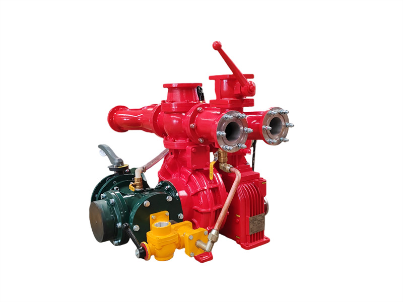
အဆိုပါ CB10/60-RS ထရပ်ကားတပ်ဆင်ထားသော မီးသတ်ပန့်သည် အဆင့်တစ်ဆင့် ဖိအားနိမ့် centrifugal ပန့်၊ ပစ္စတင်နှစ်လုံးပါ လေစုပ်ပန့်၊ လျှပ်စစ်သံလိုက်ကလပ် အလိုအလျောက် ခွဲထုတ်သည့်ကိရိယာ၊ အမြန်နှုန်းတိုးမြှင့်ကိရိယာ၊ ထွက်ပေါက်ပိုက်လိုင်းနှင့် ပိတ်ဖွင့်ဗား၊ ဝင်ပေါက်ပိုက်လိုင်းတို့ဖြင့် ဖွဲ့စည်းထားသည်။ ♦ အဓိကဖွဲ့စည်းပုံနှင့် လုပ်ဆောင်ချက် (1) အဆင့်တစ်ဆင့် ဖိအားနိမ့် centrifugal ပန့်:ပန့်အဖုံး၊ ပန့်အိမ်၊ ပထမအဆင့် impeller နှင့် ပန့်ရှပ်တို့ဖြင့် ဖွဲ့စည်းထားပြီး သတ်မှတ်ဖိအားနှင့် သတ်မှတ်စီးဆင်းနှုန်းကို ပေးစွမ်းသည်။ (2) အမြန်နှုန်းတိုးမြှင့်ကိရိယာ: CB10/60-RS ယာဉ်တပ်ဆင် မီးသတ်ပန့်၏ အမြန်နှုန်းတိုးမြှင့်ကိရိယာတွင် ပုံမှန်အမြန်နှုန်းတိုးမြှင့်အချိုး 1.440 ရှိသည်။ (3) ပစ္စတင်နှစ်လုံးပါ လေစုပ်ပန့်: အဓိကအားဖြင့် ပစ္စတင်၊ ပန့်အိမ်၊ ပန့်ရှပ်နှင့် eccentric wheel တို့ဖြင့် ဖွဲ့စည်းထားသည်။ eccentric wheel တွင် ပစ္စတင်လမ်းညွှန်တံနှင့် ပန့်အိမ် သံမဏိအိတ်တို့ကို တပ်ဆင်ထားသည်။ ပစ္စတင်ပန့်၏ အစွန်းနှစ်ဖက်တွင် ဝင်ပေါက်နှင့် ထွက်ပေါက်ဗားများ တပ်ဆင်ထားသည်။ လျှပ်စစ်သံလိုက်ကလပ် ချိတ်ဆက်သောအခါ ပစ္စတင်ပန့် စတင်အလုပ်လုပ်သည်။ လည်ပတ်နေစဉ် eccentric wheel ၏ လှည့်ပတ်လုပ်ဆောင်မှုကြောင့် ပစ္စတင်သည် အပြန်အလှန် ရွေ့လျားပြီး ပန့်နှင့် ပိုက်လိုင်းအတွင်းမှ လေကို တဖြည်းဖြည်း ထုတ်ပယ်ကာ လေထုအရည်အသွေးကို တိုးတက်စေသည်။ အခေါင်းအတွင်း လေဟာနယ် ဖြစ်ပေါ်လာပြီး ရေစုပ်ယူနိုင်ရန် ရည်ရွယ်ချက်ကို အောင်မြင်စေသည်။ 1. ထွက်ပေါက် ပိတ်ဖွင့်ဗား (၄ ခု); 2. ဘယ်နှင့်ညာ ထွက်ပေါက်ရေပိုက်များ; 3. ဂီယာဘောက် အအေးခံ ပြန်ရေချိတ်ဆက်ကိရိယာ; 4. ဖိအားတိုင်းကိရိယာ ချိတ်ဆက်ကိရိယာ; 5. ထွက်ပေါက် ပြန်မစီးဗား; 6. ရေသေနတ် flange; 7. ရေဖိအားခလုတ်; 8. PTO အအေးခံ ဖိအားပြန်ရေချိတ်ဆက်ကိရိယာ; 9. နောက်ဘက် ရေတိုင်ကီ flange; 10. နောက်ဘက် ရေတိုင်ကီ ဘောလ်ဗား; 11. ဂီယာဘောက်; 12. လျှပ်စစ်သံလိုက်ကလပ်နှင့် ဝါယာကြိုးများ; 13. ပစ္စတင် ရေဖြည့်စုပ်ပန့်; 14. လေဟာနယ်တိုင်းကိရိယာ ချိတ်ဆက်ကိရိယာ; 15. လေဟာနယ်ဖြည့် ချိတ်ဆက်ကိရိယာ; 16. ဝင်ပေါက်ပိုက် အင်တာဖေ့စ်; 17. ဝင်ပေါက် လေးလမ်းပိုက်; 18. ရေပန့် ရေထုတ်ဗား; 19. ဂီယာဘောက် အအေးခံ ဖိအားပြန်ရေပိုက်; 20. ဂီယာဘောက် အအေးခံ ဖိအားဝင်ရေပိုက်; 21. ဂီယာဘောက် ချောဆီအဆင့်ဗား; 22. ချိတ်ဆက် flange; 23. မောင်းနှင်ခါးပတ်; 24. အမြှုပ်အချိုးဖျော်စက် ဖိအားရေ ချည်ချိတ်ဆက်ကိရိယာ (ရေတင်ယာဉ်များတွင် မပါဝင်ပါ); 25. အမြှုပ်အချိုးဖျော်စက် အင်တာဖေ့စ်; 26. PTO အအေးခံ ဖိအားထွက်ရေချိတ်ဆက်ကိရိယာ; 27. CB10/60 ယာဉ် မီးသတ်ပန့်; 28. ဂီယာဘောက် အအေးခံ ဖိအားထွက်ရေချိတ်ဆက်ကိရိယာ; 29. နောက်ဘက် ဝင်ပေါက် butterfly valve (၄) ဖိအားနိမ့် ရေထွက်ပိုက်လိုင်းနှင့် ပိတ်ဖြတ်အဆို့ရှင်:ဖိအားနိမ့် ရေထွက်စစ်ဆေးအဆို့ရှင်၊ ဘယ်နှင့်ညာ ရေထွက်ပိုက်များ၊ ရေထွက်ပိုက်လေးခုနှင့် ရေထွက်ပိတ်ဖြတ်အဆို့ရှင်လေးခုတို့ဖြင့် ဖွဲ့စည်းထားသည်။ (၅) နောက်ဘက်တပ်ဆင်ထားသော ရေဝင်ပိုက်လိုင်း:လေးလမ်းသွား ရေဝင်ပိုက်၊ ရေဝင်စစ်ကာ၊ ပြင်ပရေဝင်ချိတ်ဆက်ကိရိယာတို့ဖြင့် ဖွဲ့စည်းထားပြီး၊ လေးလမ်းသွား ရေဝင်ပိုက်၏ နှစ်ဖက်တွင် ညာဘက်ခြမ်း၌ ဖုန်အချိုးညှိကိရိယာ တပ်ဆင်ရန် အင်တာဖေ့စ်တစ်ခု ပါရှိသည်။ ဘယ်ဘက်ခြမ်းတွင် လှည့်နိုင်သော နောက်ဘက်ရေဝင်ကွေးပိုက်၊ 150mm လိပ်ပြာအဆို့ရှင်နှင့် ဂဟေဆော်နိုင်သော ဖလန့်ခ်တို့ တပ်ဆင်ထားသည်။ ♦သတ်မှတ်ချက်များ မော်ဒယ် ရေဝင်ပေါက်အချင်း (mm) ရေထွက်ပေါက်အချင်း (mm) အများဆုံး လေဟာနယ် (kPa) ၁ မိနစ်အတွင်း လေဟာနယ်ကျဆင်းမှု (MPa) ၇m စုပ်ယူမှုအနက် အချိန် (s) CB10/60-RS Φ150 Φ80X4 ≥85 ≤...
အသေးစိတ်
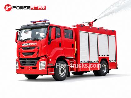
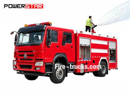
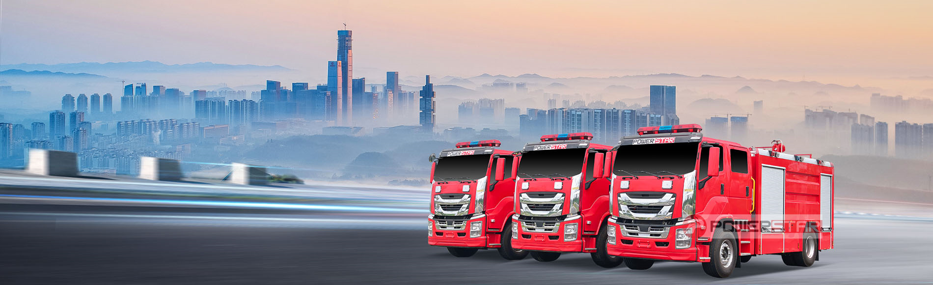
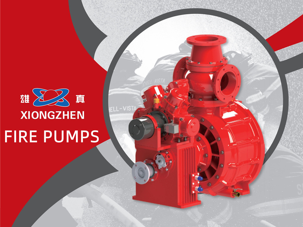
POWERSTAR သည် ပရော်ဖက်ရှင်နယ် မီးသတ်ကား ထုတ်လုပ်သူနှင့် တင်ပို့ရောင်းချသူ ဖြစ်ပါသည်။ ကျွန်ုပ်တို့၏ ထုတ်ကုန်အမျိုးအစားများတွင် ရေတိုင်ကီ မီးသတ်ကားများ၊ ဖோம் မီးသတ်ကားများ၊ ခြောက်သွေ့မှုန့် မီးသတ်ကားများနှင့် လှေကားအမြင့် မီးသတ်ကားများ ပါဝင်ပြီး မြို့ပြ မီးငြိမ်းသတ်ရေး၊ ရေနံဓာတုစက်ရုံများ၊ လေဆိပ်များနှင့် ဆိပ်ကမ်းများ၊ သစ်တောမီး ကာကွယ်ရေးနှင့် အခြားလုပ်ငန်းများတွင် ကျယ်ပြန့်စွာ အသုံးပြုကြပါသည်။ ISUZU၊ HOWO နှင့် FAW ကိုယ်ထည်များအပေါ် အခြေခံထားသော ကျွန်ုပ်တို့၏ မီးသတ်ကား မော်ဒယ်များကို အရှေ့တောင်အာရှ၊ အရှေ့အလယ်ပိုင်း၊ တောင်အမေရိကနှင့် အာဖရိကရှိ နိုင်ငံများနှင့် ဒေသများစွာသို့ တင်ပို့ရောင်းချထားပါသည်။ ဖိလစ်ပိုင်အစိုးရ၏ အမြောက်အများ ဝယ်ယူမှုများမှ နိုင်ဂျီးရီးယား ဖောက်သည်များ၏ ထပ်မံမှာယူမှုများအထိ POWERSTAR သည် ယုံကြည်စိတ်ချရသော အရည်အသွေးနှင့် ပရော်ဖက်ရှင်နယ် စိတ်ကြိုက်ပြင်ဆင် ဝန်ဆောင်မှုများဖြင့် ကမ္ဘာလုံးဆိုင်ရာ ဖောက်သည်များအကြား ခိုင်မာသော နာမည်ကောင်း ရရှိထားပါသည်။ POWERSTAR သည် XIONGZHEN မီးသတ်ပန့်များကို အဘယ်ကြောင့် ရွေးချယ်သနည်း။မီးသတ်ပန့်ကို မီးသတ်ကား၏ "နှလုံးသား" ဟု မကြာခဏ ခေါ်ဆိုကြပါသည်—ထိရောက်မှုမြင့်မားပြီး ယုံကြည်စိတ်ချရသော မီးသတ်ပန့် မရှိပါက မီးသတ်ကားသည် ပစ္စည်းကိရိယာများနှင့် ဝန်ထမ်းများကို သယ်ယူပို့ဆောင်ရန်သာ အသုံးပြုနိုင်သော ယာဉ်တစ်စီးသာ ဖြစ်ပြီး မီးငြိမ်းသတ်ရေး တာဝန်များကို အမှန်တကယ် ဆောင်ရွက်နိုင်မည် မဟုတ်ပါ။ ထိုအကြောင်းကြောင့် POWERSTAR သည် အဓိကအစိတ်အပိုင်းများကို ရွေးချယ်ရာတွင် အမြင့်ဆုံး စံနှုန်းများကို လိုက်နာပါသည်။XIONGZHEN သည် တရုတ်နိုင်ငံ၏ မီးသတ်ပန့်လုပ်ငန်းတွင် လူသိများသော အမှတ်တံဆိပ်တစ်ခုဖြစ်ပြီး ၎င်း၏ ထုတ်ကုန်များကို နိုင်ငံတစ်ဝန်းရှိ ပရော်ဖက်ရှင်နယ် မီးသတ်ကား ထုတ်လုပ်သူများစွာက ကျယ်ပြန့်စွာ အသုံးပြုကြပါသည်။ ဂျာမနီ၊ ဩစတြီးယား၊ အမေရိကန်နှင့် အခြားနိုင်ငံများ၏ အဆင့်မြင့် နည်းပညာများကို ကိုယ်ပိုင် R&D စွမ်းအားများနှင့် ပေါင်းစပ်တည်ဆောက်ထားသော XIONGZHEN သည် တင်သွင်းကုန်ပစ္စည်းများနှင့် ယှဉ်ပြိုင်နိုင်သော စွမ်းဆောင်ရည်ရှိသည့် ယာဉ်တပ်ဆင် မီးသတ်ပန့် စီးရီးများကို ပေးစွမ်းပါသည်။ အဓိက အားသာချက်များမှာ:• ထူးချွန်သော စွမ်းဆောင်ရည်နှင့် မြင့်မားသော ထိရောက်မှု:နှစ်ဆင့် centrifugal impeller နှင့် လမ်းညွှန်ဗိန်း ပါဝင်သော ပန့်အိမ် ဒီဇိုင်းသည် ပန့်ရှပ်ပေါ်ရှိ radial နှင့် axial အားများကို ချိန်ညှိပေးပြီး ချောမွေ့ကာ ထိရောက်သော လည်ပတ်မှုကို အာမခံပါသည်။• ကျစ်လစ်သော ဖွဲ့စည်းပုံနှင့် ရိုးရှင်းသော လည်ပတ်အသုံးပြုမှု:လမ်းညွှန်ဗိန်းခန်းနှင့် ဖိအားခန်းတို့၏ ပေါင်းစပ်ဒီဇိုင်းသည် ပြုပြင်ထိန်းသိမ်းခြင်းနှင့် ဝန်ဆောင်မှုပေးခြင်းကို အဆင်ပြေစေပါသည်။• ဆန်းသစ်သော ရေစုပ်တင်နည်းပညာ:လျှပ်စစ်သံလိုက် clutch ပါဝင်သော piston လေးလုံးပါ လျှပ်စစ်ရေစုပ်တင်ပန့်သည် ရေဝင်ရောက်မှု ပိုမိုကောင်းမွန်ပြီး ရိုးရာ piston နှစ်လုံးပါ ပန့်များထက် စုပ်ယူမှု စွမ်းဆောင်ရည် ပိုမိုမြင့်မားပါသည်။ ရေမရှိသော အခြေအနေများတွင် mechanical seal များ ခြောက်သွေ့လည်ပတ်၍ ပျက်စီးမှု ဖြစ်ပေါ်ခြင်းကို ထိရောက်စွာ ကာကွယ်ပေးပါသည်။• အာဏာပိုင် အသိအမှတ်ပြုလက်မှတ်:ထုတ်ကုန်စီးရီးတစ်ခုလုံးသည် National Fire Equipment Quality Supervision and Inspection Center ၏ အမျိုးအစား စမ်းသပ်မှုကို အောင်မြင်ပြီး GB6245-2006 စံနှုန်းနှင့် ကိုက်ညီပါသည်။ POWERSTAR သည် XIONGZHEN မီးသတ်ပန့်များကို ၎င်းတို့၏ ယုံကြည်စိတ်ချရသော အရည်အသွေးနှင့် သက်သေပြပြီးသော နည်းပညာကြောင့် ရွေးချယ်ခြင်းဖြစ်ပြီး ကျွန်ုပ်တို့၏ စက်ရုံမှ ထွက်ရှိသ...
အသေးစိတ်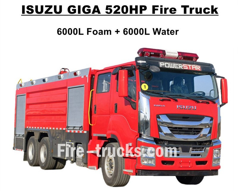
အရည်အသွေးမြင့်ISUZU GIGA မီးသတ်ကားများအနောက်အာဖရိက Burkina Faso သို့ တင်ပို့ရန် ဒီဇိုင်းပြုလုပ်ထားသော ISUZU GIGA VC66 အလေးစား 6x4 ထရပ်ကားကိုယ်ထည်ပေါ် အခြေခံထားပြီး GIGA VC66 အသစ်ခန်းကို အသုံးပြုထားသည်။ စံလေအားဆိုင်းထိန်းထိုင်ခုံနှင့် လေအေးပေးစက် ပါဝင်၍ သက်တောင့်သက်သာ မောင်းနှင်နိုင်သည်။ ဂျပန် ISUZU နည်းပညာ ဒီဇယ်အင်ဂျင် 6WG1-TCG62 မော်ဒယ်၊ 520HP နှင့် အင်ဂျင်ထုတ်လွှတ်ပမာဏ 15681cc ပါဝင်ပြီး FAST 12 အဆင့် လက်ဖြင့်ပြောင်းဂီယာဘောက်စ်နှင့် တွဲဖက်အလုပ်လုပ်သည်။ လောင်စာသုံးစွဲမှု အလွန်နည်းပါးပြီး ရှေ့ဘီး 385/80R22.5 နှင့် နောက်ဘီး 315/80R22.5 ကို စံအဖြစ် အသုံးပြုထားကာ စုစုပေါင်း 10+1 ယူနစ် ပါဝင်သည်။ အပေါ်ပိုင်းတပ်ဆင်ပစ္စည်းများတွင် ရေတိုင်ကီ 6000L နှင့် ဖိုမ်တိုင်ကီ 6000L ပါဝင်ပြီး အားလုံးကို သံမဏိ #304 ပစ္စည်းဖြင့် ပြုလုပ်ထားသဖြင့် တာရှည်အသုံးပြုနိုင်သည်။ စိတ်ကြိုက်ပြင်ဆင်ထားသော အလွန်အားကောင်းသော CB10/140 မီးသတ်ပန့်နှင့် တွဲဖက်ထားပြီး စီးဆင်းနှုန်း 140L/s ရှိသည်။ တိုင်ကီကိုယ်ထည်အပေါ်ရှိ နှစ်ထပ်မီးသတ်ပန့်စနစ်နှင့် တွဲဖက်ကာ မော်ဒယ် PL8/64 နှင့် စီးဆင်းနှုန်း 64L/s ရှိသည်။ISUZU GIGA 520HP မီးသတ်အင်ဂျင်လိုအပ်သော မီးသတ်ကိရိယာများအားလုံးနှင့် တွဲဖက်ထားပြီး မီးငြှိမ်းသတ်ခြင်းနှင့် လူကယ်ဆယ်ရေးအတွက် အကောင်းဆုံး မီးသတ်ယာဉ်ဖြစ်ကာ Burkina Faso ဈေးကွက်တွင် ကျယ်ပြန့်စွာ အသုံးပြုသ
အသေးစိတ်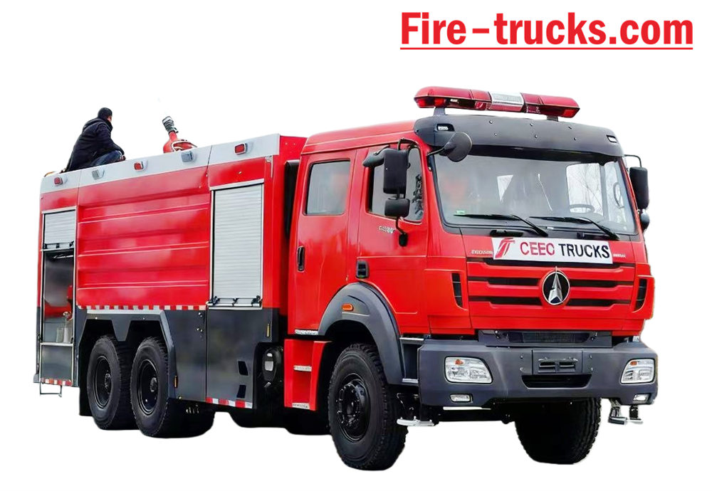
ဘိုင်ဘန် Type II Beiben 2638 မော်ဒယ် 6*4 ဘယ်ဘက်လက်မောင်း ကိုယ်ထည်၊ ကိုယ်ထည်ကို အခြေခံထားသော မီးသတ်ကား ၁၀၀၀၀ လီတာ ရေတိုင်ကီနှင့် ၂၀၀၀ လီတာ ရေမြှုပ်တိုင်ကီ အပါအဝင် လီတာ ၁၂၀၀၀ အထိ ဆံ့သည်။ Beiben 2638 မီးသတ်ကယ်ဆယ်ရေး ထရပ်ကား XIONGZHEN CB10/60 မီးသတ်စုပ်စက်နှင့် PL8/48 မီးငြှိမ်းသတ်စောင့်ကြည့်စနစ် တပ်ဆင်ထားသောကြောင့် အလွန်အဆင်ပြေပါသည်။ နေ့စဉ်သုံးစွဲမှု။ အဓိကအားဖြင့် လိုအပ်သည့်နေရာများတွင် မီးငြှိမ်းသတ်ရေးစီမံကိန်းအတွက် အသုံးပြုသည်။ Beiben အမှတ်တံဆိပ် ထရပ်ကားကိုယ်ထည်၏ အားသာချက်များကို အပြည့်အဝ အားကိုးအားထားပြု၍ ဒီဇိုင်းထုတ်ထားသော ယာဉ်၊ ထုတ်ကုန်၏ အဆင်ပြေမှုနှင့် ယုံကြည်စိတ်ချရမှုအပြင် အသစ်ဒီဇိုင်းထုတ်ထားသော ကိုယ်ထည်ကိုပါ အပြည့်အဝ ထည့်သွင်းစဉ်းစားပါ။ ကိုယ်ထည် ပစ္စည်းက နိုင်ငံတကာစံနှုန်း ကာဗွန်သံမဏိဖြစ်ပြီး သံချေးမတက်အောင် ဆေးသုတ်ထားတဲ့အပြင် သံမဏိလည်း ပါဝင်ပါတယ်။ သံချေးတက်ခြင်းကို ရှောင်ရှားရန်နှင့် သက်တမ်းကြာရှည်စွာ ဝန်ဆောင်မှုပေးနိုင်ရန် ထိရောက်စွာ လုပ်ဆောင်နိုင်သည်။ Beiben 6x4 မီးသတ်ကားတွင် Sandwich PTO၊ မီးသတ်စုပ်စက်၊ မီးသတ်စောင့်ကြည့်ကိရိယာ၊ ဝန်ထမ်းအခန်း၊ ရေပိုက်တို့ တပ်ဆင်ထားသည်။ သေတ္တာ၊ ပန့်ခန်း၊ ခြောက်သွေ့သော အမှုန့်တင်သင်္ဘောနှင့် နိုက်ထရိုဂျင်စနစ်၊ ပိုက်လိုင်းပိုက်လိပ်နှင့် တွဲဖက်ထားသည်၊ အင
အသေးစိတ်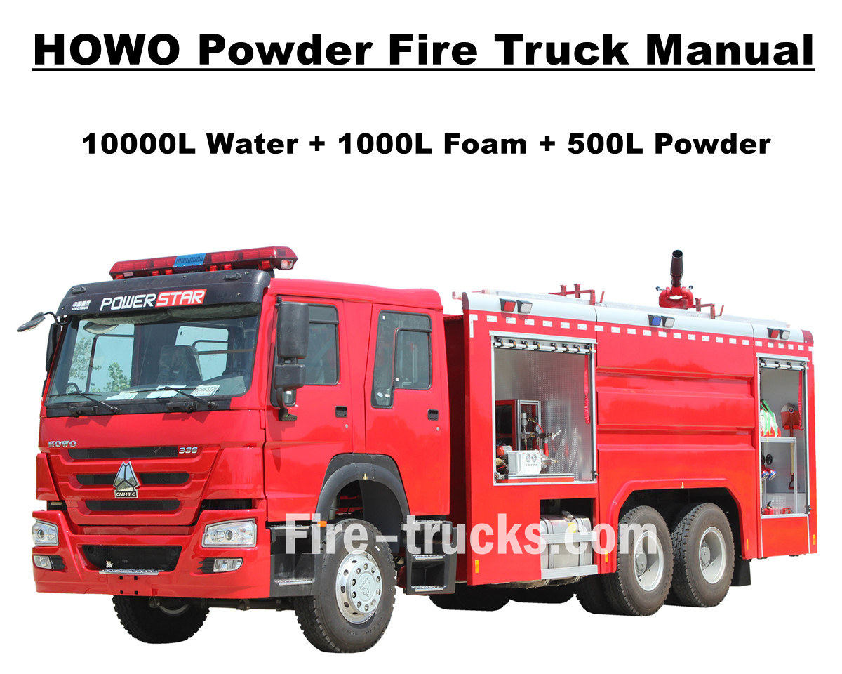
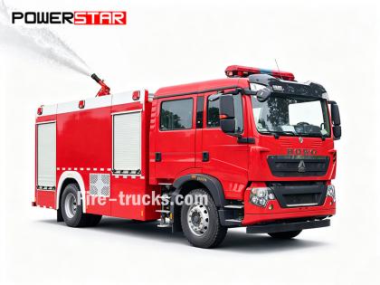
အာဖရိက မောရစ်တေးနီးယား ဖောက်သည်သည် စုစုပေါင်း ၄ ယူနစ် ဝယ်ယူခဲ့သည် Sinotruk HOWO pumper မီးသတ်အင်ဂျင် POWERSTAR TRUCKS မှဖြစ်ပြီး မြို့တော် Nouakchott တွင် အသုံးပြုသည်။ မီးသတ်ကားကို မီးသတ်အင်ဂျင်နှင့် မီးသတ်စုပ်စက်ဟုလည်း ခေါ်ဆိုနိုင်ပြီး ၎င်းသည် နိုင်ငံတကာတွင် မီးငြှိမ်းသတ်ခြင်းနှင့် လူကယ်ဆယ်ရေးစီမံကိန်းများစွာ၏ လိုအပ်ချက်များကို ဖြည့်ဆည်းရန် ဒီဇိုင်းထုတ်ပြီး ထုတ်လုပ်ထားသော ယာဉ်တစ်စီးဖြစ်သည်။ မီးသတ်သမားတင်ဆောင်ရန်အတွက် စိတ်ကြိုက်ပြုလုပ်ထားသော နှစ်ထပ်ခန်းတွဲ၊ မီးငြှိမ်းသတ်ခြင်း၊ မီးကယ်ဆယ်ရေးစသည့် မီးသတ်ပစ္စည်းကိရိယာများနှင့် ကိရိယာများ။ HOWO မီးသတ်ကားများ ပိုမိုထိရောက်စွာ အလုပ်လုပ်နိုင်စေရန်အတွက်၊ အလူမီနီယမ်သတ္တုလှေကားများ၊ ရေမြှုပ်နှင့် ခြောက်သွေ့သောအမှုန့်မီးသတ်ဆေးနှင့် သိုလှောင်ကန်များ၊ ထိရောက်စွာ မီးသတ်စုပ်စက် CB10/60 မော်ဒယ်ကို PL8/48 မီးစောင့်ကြည့်ကိရိယာနှင့် ကိုက်ညီစေပြီး မီတာ ၇၀ ကျော်အကွာအဝေးကို ထိရောက်စွာ ဖြန်းနိုင်စေရန်၊ အဝေးထိန်းမီးငြှိမ်းသတ်ရန်အတွက် သေနတ်ပါသော မီးသတ်ပိုက်ရီးလ်၊ မျက်နှာဖုံးပါသော အသက်ရှူကိရိယာ၊ အကာအကွယ်အဝတ်အစား၊ ကယ်ဆယ်ရေးကိရိယာများ၊ အရေးပေါ်ဆေးသေတ္တာစသည်တို့ တပ်ဆင်ထားရန် ကျွန်ုပ်တို့ စိတ်ကြိုက်ပြုလုပ်ထားပါသည်။ HOWO မီးသတ်ကားများအတွက် ထိရောက်စွာနှင့် ယုံကြည်စိတ်ချရသော အလုပ်လုပ်မှုအတွက် ဝန်ဆောင်မှုအားလုံး။ Mauritania သုံးစွဲသူများသည် HOWO မီးသတ်ကားကို ပိုမိုလွယ်ကူစွာနှင့် ထိရောက်စွာ အသုံးပြုနိုင်ကြောင်း သေချာစေရန်၊ ထရပ်ကားအားလုံးတွင် ဝန်ဆောင်မှုအတွက် အင်္ဂလိပ်ဗားရှင်းကတ်တလောက်အပြည့်အစုံနှင့် ကိုက်ညီပြီး လည်ပတ်မှုလမ်းညွှန်အတွက် အသုံးပြုသူလက်စွဲ၊ ထရပ်ကားလက်စွဲနှင့် အသုံးပြုမှုနှင့် ပြုပြင်ထိန်းသိမ်းမှုအတွက် အပိုပစ္စည်းများလက်စွဲတို့ ပါဝင်သည်။ SINOTRUK HOWO 14,000L အမှုန့်စုပ်စက် မီးသတ်ကား POWERSTAR စက်ရုံ ထရပ်ကားဧရိယာတွင် ပရော်ဖက်ရှင်နယ်ထုတ်လုပ်သူဖြစ်ပြီး၊ ထုတ်ကုန်အားလုံးသည် အသစ်စက်စက်နှင့် အရည်အသွေးမြင့်ဖြစ်ကြောင်း အာမခံပါသည်။ » ၁။ HOWO မီးသတ်ကား၏ အားသာချက်များ- ★ 247KW / 336HP အစွမ်းထက် WEICHAI ဒီဇယ်အင်ဂျင်၊ ပြဿနာမရှိဘဲ 100,000 Km။ ★ SINOTRUK HOWO ဂန္ထဝင် HW76 ကားအတွင်းခန်း၊ ဥရောပဒီဇိုင်း ★ တပ်ဆင်ထားသော CB10/60 မီးသတ်စုပ်စက်၊ တစ်စက္ကန့်လျှင် 60 လီတာ ရေစီးနှုန်း၊ အလွန်ယုံကြည်စိတ်ချရပါသည် ★ အပေါ်ဆုံးတွင်တပ်ဆင်ထားသော PL8/48 ရေမီးသေနတ်၊ တာရှည်ခံဝန်ဆောင်မှု ★ လေထိန်းချုပ်အဆို့ရှင်များပါသည့် နိုက်ထရိုဂျင်ပုလင်းပါသည့် 500L ခြောက်သွေ့သောအမှုန့် ★ အမြှုပ်နှင့် အမှုန့်အတွက် ပေါင်းစပ်ထိန်းချုပ်မှုစနစ်၊ နောက်ဘက်တွင် panel ပါရှိသည် » ဒုတိယ ။ Howo ကယ်ဆယ်ရေး မီးသတ်ကားပုံဆွဲခြင်း- [if gte mso 9]> Normal 0 ၇.၈ ရုပ်ပုံ ၀ ၂ false false false EN-US ZH-CN AR-SA SemiHidden="true" UnhideWhenUsed="true" Name="List Number"/> Exception: SemiHidden="true" UnhideWhenUsed="true" Name="Body Text Indent"/> Locked="false" SemiHidden="true" UnhideWhenUsed="true" Name="E-mail Signature"/> " Name="1" /* Style Definitions */ table.MsoNormalTable {mso-style-name:普通表格; mso-tstyle-rowband-size:0; mso-tstyle-colband-size:0; mso-style-noshow:yes; mso-style-priority:99; mso-style-parent:""; mso-padding-alt:0cm 5.4pt 0cm 5.4pt; mso-para-margin:0cm; mso-pagination:widow-orphan; font-size:10.0pt; font-family:"Calibri",sans-serif; mso-bidi-font-family:"Times New Roman";} To guarantee Mauritania Nouakchott clients purchased satisfy HOWO 6x4 Water & Foam & Powder Fire Tr...
အသေးစိတ်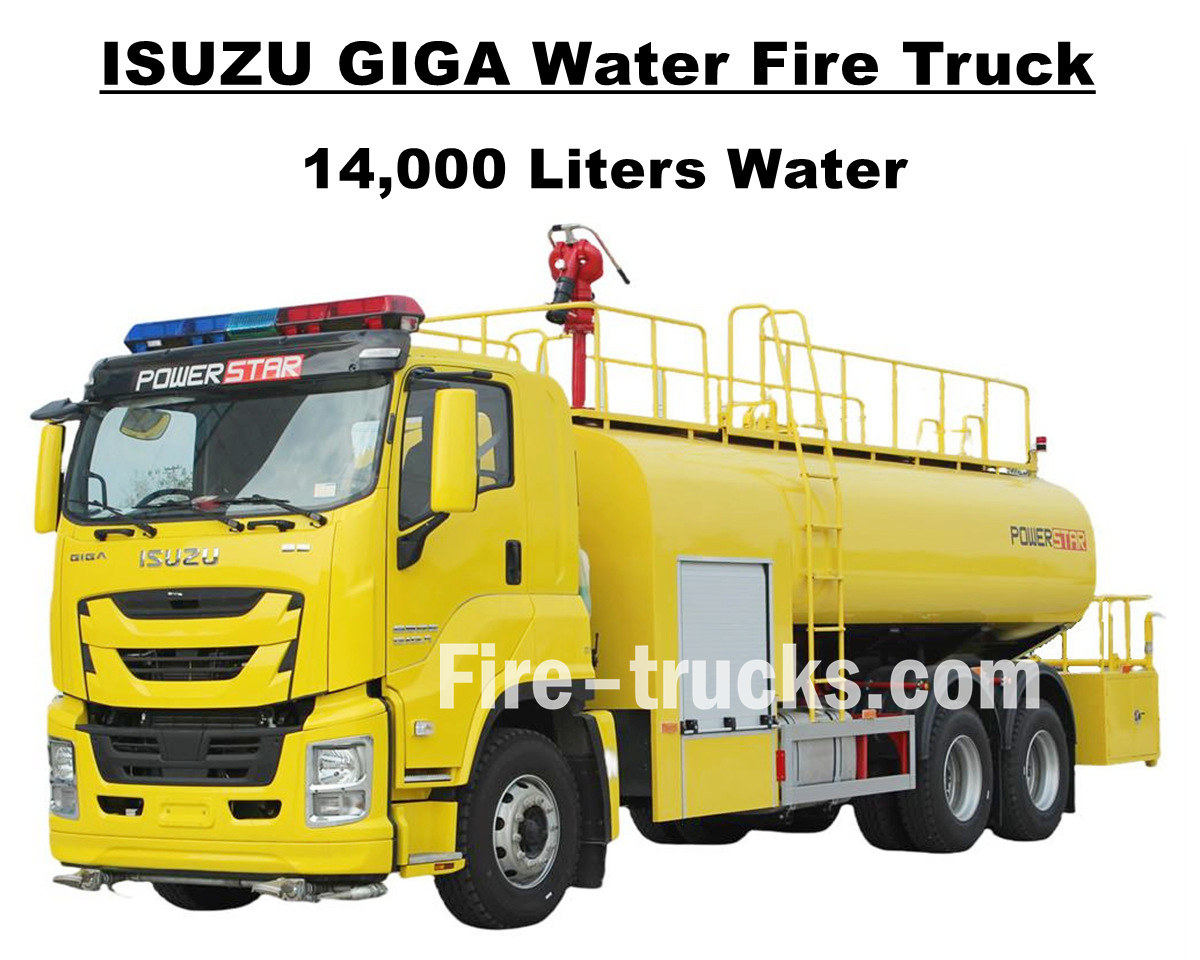
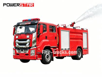
1 ယူနစ်ကို ဝယ်ယူခဲ့သော Hondura မှ တောင်အမေရိက ဖောက်သည် Mr Joseph Isuzu GIGA VC66 14000L 3700gallons ရေမီးငြိမ်းသတ်ထရပ်ကား POWERSTAR TRUCKS မှ၊ ဂျပန် ISUZU GIGA 6x4 အကြီးစား ထရပ်ကား ကိုယ်ထည်ကို အခြေခံ၍ ဒီဇိုင်းထုတ်ထားသည့် 6UZ1-TCG60 မော်ဒယ် ဒီဇယ်အင်ဂျင်ပါဝါ 280kw / 380HP မြင်းကောင်ရေ 280kw / 380HP တပ်ဆင်ထားသော ဆလင်ဒါ 6 လုံး၊ 4-stroke၊ water-cooled, turbocharged and intercooled engine, အပြည်ပြည်ဆိုင်ရာ စံသတ်မှတ်ချက် 283 နှင့် ထိရောက်စွာ ရွှေ့ပြောင်းနိုင်သော AST 283 နှင့် ကိုက်ညီပါသည်။ ဂီယာဘောက်စ်၊ ရှေ့သို့ 12 ဆိုင်း နှင့် နောက်သို့ 2 ဆိုင်း ၊ ဆီစားသုံးမှုကို ထိရောက်စွာ လျှော့ချနိုင်ပြီး မော်ဒယ် 12R22.5 မော်ဒယ် ပါသော စတီးတာယာ 13 လုံး တပ်ဆင်ထားပြီး အပိုတာယာ တစ်လုံး အပါအဝင်၊ လမ်းအခြေအနေ အမျိုးမျိုးအတွက် အလွန်သင့်လျော်ပြီး တောင်တက်ရန်အတွက် အလွန်သင့်လျော်ပါသည်။ Wheelbase ကို 4600+1370mm ဖြင့် ရွေးချယ်နိုင်သည်၊ ဧရိယာအများအပြားအတွက် မီးသတ်ဆေးဘူးပရောဂျက်အတွက် သင့်လျော်ပြီး အဆင်ပြေစေရန် ဒီဇိုင်းထုတ်ထားသော ဝန်ဆောင်မှု။ Isuzu GIGA 3700 ဂါလံ ရေတင်သင်္ဘော မီးသတ်အင်ဂျင်သည် ဂျပန်နည်းပညာ ISUZU ထရပ်ကားကိုယ်ထည်၊ မူရင်း GIGA VC66 ဗီရိုကို အပြည့်အဝ အားကိုးပြီး သက်တောင့်သက်သာ မောင်းနှင်နိုင်ရန် အပူပေးအအေးပေးစနစ်ပါရှိသော A/C တပ်ဆင်ထားပါသည်။ သံမဏိ SS304 ပစ္စည်းအပြည့်အစုံဖြင့် တပ်ဆင်ထားသော ထရပ်ကားသည် ထုထည် 14000 လီတာ ၃၇၀၀ ဂါလံနှင့် ညီမျှသော ထိရောက်စွာ ပမာဏ 14000 လီတာဖြင့် တပ်ဆင်ထားသော တရုတ်အမှတ်တံဆိပ် CB10/60 မီးသတ်ပန့်နှင့် PS8/50 မီးသတ်မော်နီတာတစ်လုံး၊ ရေနံတင်သင်္ဘောကိုယ်ထည်ထိပ်တွင် မီးသတ်ဆေးဘူး အစုံအလင် အစုံအလင်နှင့် ကုန်တင်ကားကြီးတစ်ခုလုံးအတွက် သံပုရာအဝါရောင် ပန်းချီကားများ တပ်ဆင်ထားပြီး၊ အားလုံးသည် ကားတစ်စီးလုံးအတွက် စိတ်ကူးဖြင့် မီးငြှိမ်းသတ်ရန် စိတ်ကူးရှိနေသည်။ အသိုင်းအဝိုင်း။ ထရပ်ကားသည် လည်ပတ်လမ်းညွှန်မှုအတွက် အသုံးပြုသူ၏လက်စွဲ၊ GIGA ထရပ်ကားအသုံးပြုမှုအတွက် ထရပ်ကားလက်စွဲ၊ ပြုပြင်ထိန်းသိမ်းမှုအတွက် Spare Parts Manual အပါအဝင် ဝန်ဆောင်မှုအတွက် အစုံအလင် အင်္ဂလိပ်ဗားရှင်းကတ်တလောက်နှင့် တွဲဖက်ထားသော ထရပ်ကား။ Isuzu GIGA 14,000L Water Pumper Fire Fighting ထရပ်ကား POWERSTAR စက်ရုံ ထရပ်ကားဧရိယာတွင် ကျွမ်းကျင်ထုတ်လုပ်သူ၊ Brand-New နှင့် High-Quality ထုတ်ကုန်အားလုံးကို အာမခံပါသည်။ » Ⅰ။ Isuzu Water Fire Truck ၏ အားသာချက်များ ★ 280KW / 380HP အားကောင်းသော 6WG1 ဒီဇယ်အင်ဂျင်၊ prblem မပါဘဲ 100,000 Km ။ ★ ISUZU VC66 အသစ်စက်စက် GIGA cabin၊ ဥရောပဒီဇိုင်း ★ တပ်ဆင်ထားသော CB10/60 မီးသတ်ပန့်၊ 60L/s စီးဆင်းမှုနှုန်း၊ အလွန်စိတ်ချရသည်။ ★ ထိပ်တန်းတပ်ဆင်ထားသော PS8/50 ရေမီးအမြောက်၊ အကြမ်းခံသောဝန်ဆောင်မှု ★ ဘေးဘက်တွင် panel ပါရှိသော ပေါင်းစပ်ထိန်းချုပ်မှုစနစ် ★ စိတ်ကြိုက်သံပုရာအဝါရောင်ပန်းချီကား၊ တောက်ပပြီး လှပသည်။ CB10/60 မီးသတ်ပန့် မော်ဒယ် : CB10/60 ဖိအား : 1.0Mpa မက်တယ်။ အလုပ်ဖိအား : 1.232Mpa စီးဆင်းမှုနှုန်း : 1.0Mpa တွင် 60L/s၊ အမြန်နှုန်း 3286±50r/min၊ ပါဝါ 102kW၊ suction depth 3m 1.3Mpa တွင် 42L/s၊ အမြန်နှုန်း 3519±50r/min၊ ပါဝါ 106kW၊ suction depth 3m 1.0Mpa တွင် 30L/s၊ အမြန်နှုန်း 3120±50r/min၊ ပါဝါ 73kW၊ suction depth 7m မြန်နှုန်းအချိုး : ၁:၁.၄၄ PS8/50 Fire Monitor မော်ဒယ် : PS8/50 ဖိအား : 0.8Mpa လုပ်ငန်းခွင် : ရေ ≥ ၆၅ ဍ ဒေါင်လိုက် လှည့်ခြင်း။ : -45° ~ +70° အလျားလိုက်လှည့်ခြင်း။ : 0° ~ 360° စီးဆင်းမှုနှုန်း : ၅၀ L/s » Ⅱ . Isuzu Fire Pumper Truck ရေးဆွဲခြင်း- ISUZU GIGA VC66 14000L ရေတ...
အသေးစိတ်
Powerstar Trucks သည် စိတ်တိုင်းကျ အရေးပေါ်တုံ့ပြန်ရေးယာဉ်များနှင့် ထုတ်လုပ်သည်။ မီးသတ်ကားများ နှစ်ပေါင်းများစွာကြာအောင် Powerstar ထရပ်ကားများ အရေးပေါ်တုံ့ပြန်ရေးသည် ကျွမ်းကျင်မှုဖြင့် စိတ်ကြိုက်မီးယန္တရား၏ ထိပ်တန်းထုတ်လုပ်သူအဖြစ် ၎င်း၏အမွေအနှစ်ကို ထူထောင်ခဲ့သည်။ ရေမြှုပ် မီးသတ်ကားများ နှင့် ကယ်ဆယ်ရေးယာဉ် . မီးသတ်သမားများ ယုံကြည်စိတ်ချရသော အမွေအနှစ်များကို တည်ဆောက်ခြင်းဖြင့် Powerstar ထရပ်ကားများသည် ထူးခြားသော မီးသတ်ဌာနလိုအပ်ချက်တစ်ခုစီကို ဖြည့်ဆည်းပေးနိုင်ရန် လိုက်လျောညီထွေရှိသော၊ ဗျူဟာမြောက်၊ အထူးပြုဖြေရှင်းချက်များကို ပေးဆောင်ကာ ပထမဦးစွာ တုံ့ပြန်သူများကို ဦးစွာဦးစားပေးပါသည်။ ကယ်ဆယ်ရေးယာဉ် အစီးရေ ၁၂၀ ဖြင့် ပို့ဆောင်ပေးခဲ့ပါသည်။ ယူဂန်ဒါ ရဲတပ်ဖွဲ့သို့ ကယ်ဆယ်ရေး မီးသတ်ကား အစီး ၆၅ စီး တင်ပို့ခဲ့သည်။ မီးသတ်ကားများ ရေမြှုပ်မီးငြှိမ်းသတ်ယာဉ် မီးသတ်ကားများကို ၎င်းတို့၏လုပ်ငန်းဆောင်တာအရ အဓိကအားဖြင့် လေးမျိုးခွဲခြားထားသည်- မီးသတ်ထရပ်ကားများ၊ ဝေဟင်လှေကားထရပ်ကားများ၊ အထူးရည်ရွယ်ချက် မီးသတ်ကားများနှင့် ထောက်ပံ့ပို့ဆောင်ရေး မီးသတ်ကားများ။ ၀၁၊ မီးသတ်ကားများ မီးကို တိုက်ရိုက်ငြှိမ်းသတ်ရန် အဓိက အင်အားစုများ ဖြစ်ကြသည်၊၊ * ** Water Tank Fire Trucks :** ယေဘူယျ မီးငြှိမ်းသတ်ရန်အတွက် သင့်လျော်သော ၎င်းတို့၏ ကိုယ်ပိုင်ရေတိုင်ကီနှင့် ပန့်များ တပ်ဆင်ထားပါသည်။ * ** Foam Fire Trucks :** ဆီကဲ့သို့သော မီးလောင်လွယ်သော အရည်များ ပါဝင်သော မီးများကို ငြှိမ်းသတ်ရန်အတွက် အထူးထုတ်လုပ်ထားပါသည်။ * ** Dry Powder Fire Trucks :** ဓာတ်ငွေ့နှင့် လျှပ်စစ်မီးများကို ငြှိမ်းသတ်ရန် သင့်လျော်သည်။ * ** ကာဗွန်ဒိုင်အောက်ဆိုဒ် မီးသတ်ကားများ-** အဖိုးတန် ပစ္စည်းများနှင့် တိကျသော တူရိယာများကို ကာကွယ်ရန်အတွက် အသုံးပြုသည်။ * **Foam-Dry Powder ပေါင်းစပ်အသုံးပြုမှု ထရပ်ကားများ-** ကျယ်ပြန့်သော အပလီကေးရှင်းများဖြင့် မီးသတ်ဆေးရည် နှစ်မျိုးလုံးကို တစ်ပြိုင်နက် အသုံးပြုနိုင်သည်။ ၀၂၊ ဝေဟင်လှေခါး မီးသတ်ကားများ အထပ်မြင့် အဆောက်အအုံများတွင် အဓိကအားဖြင့် ကယ်ဆယ်ရေးနှင့် မီးငြှိမ်းသတ်ရာတွင် အသုံးပြုကြသည်၊ * ** လှေကား မီးသတ်ကားများ :** လူများကို ကယ်ဆယ်နိုင်ပြီး အမြင့်တွင် မီးငြှိမ်းသတ်နိုင်သည့် တယ်လီစကုပ်လှေကားပါရှိသည်။ * **Aerial Spray Fire Trucks-** အဝေးထိန်းစနစ်ဖြင့် ထိန်းချုပ်ထားသော boom ကို အသုံးပြု၍ အကွာအဝေးတွင် မီးသတ်ဆေးဖြန်းခြင်းများ ပြုလုပ်ပါ။ * ** ဝေဟင်ပလပ်ဖောင်း မီးသတ်ကားများ-** ကယ်ဆယ်ရေးနှင့် မီးငြှိမ်းသတ်ရန်အတွက် ဟိုက်ဒရောလစ် ဓာတ်လှေကား ပလပ်ဖောင်းတစ်ခု ပေးဆောင်ပါ။ မီးသတ်ကားလျှောက်လွှာ 03၊ အထူးပြုမီးသတ်ယာဉ်များသည် အောက်ပါကဲ့သို့သော သီးခြားလုပ်ငန်းတာဝန်များအတွက် တာဝန်ရှိပါသည်။ * ** ကယ်ဆယ်ရေးနှင့် သဘာဝဘေးအန္တရာယ် ကယ်ဆယ်ရေး မီးသတ်ကားများ-** မတော်တဆမှု ကယ်ဆယ်ရေးအတွက် အသုံးပြုသည့် ဖြိုဖျက်ကိရိယာများနှင့် ရုတ်သိမ်းသည့်ကိရိယာများ တပ်ဆင်ထားသည်။ * **မီးထွန်းကားများ-** ညအချိန် ကယ်ဆယ်ရေး လုပ်ငန်းများ အတွက် ပြင်းထန်မှု မြင့်မားသော အလင်းရောင် ပေးဆောင်ပါ။ * **မီးခိုးထုတ်သည့် မီးသတ်ကားများ-** မြေအောက်မီးလောင်ကျွမ်းမှုတွင် မီးခိုးထုတ်ယူခြင်းလုပ်ငန်းအတွက် အသုံးပြုသည်။ 04၊ **ထောက်ပံ့ပို့ဆောင်ရေးဆိုင်ရာ မီးသတ်ထရပ်များ-** မီးဘေးအခင်းဖြစ်ပွားရာသို့ ထောက်ပံ့ပို့ဆောင်ရေးဆိုင်ရာ ပံ့ပိုးကူညီမှုများ ပံ့ပိုးပေးပါသည်။ * **ရေပေးဝေရေး မီးသတ်ကားများ-** ရှေ့တန်းရှိ မီးသတ်ကားများအား စဉ်ဆက်မပြတ် ရေပေးဝေပေးခြင်း၊ **ပစ္စည်းကိရိယာ မီးသတ်ကားများ-** သယ်ယူ ပို့ဆောင်ခြင်းနှင့် အမျိုးမျိုးသော မီးငြှိမ်းသတ်ရေး ကိရိယာများ ဖြည့်စွက်ခြင်း။ Powerstar ထ...
အသေးစိတ်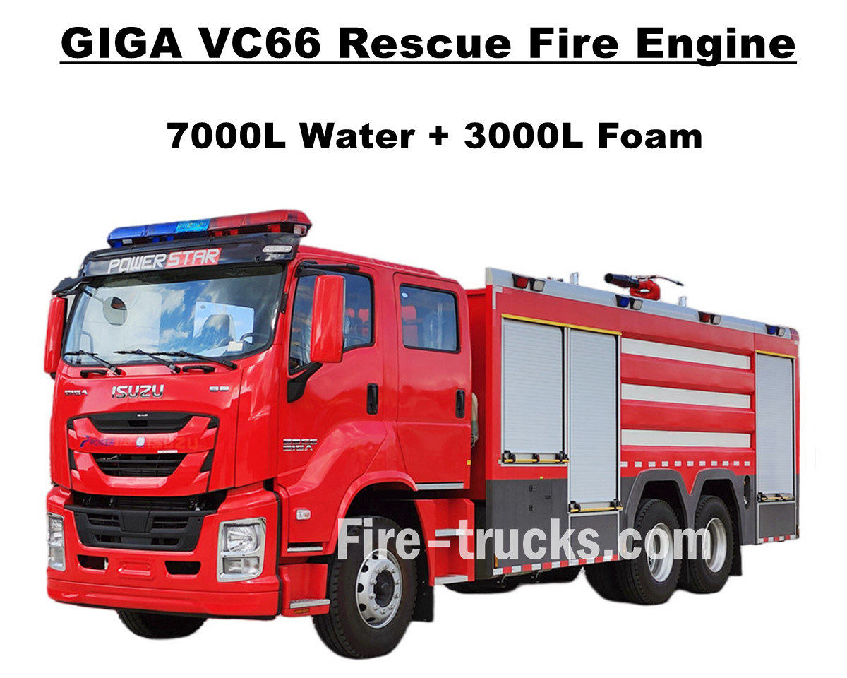
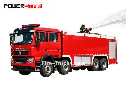
ဖိလစ်ပိုင် မနီလာတွင် ဝယ်ယူသူများ Isuzu GIGA VC66 အကြီးစား မီးသတ်ယာဉ် POWERSTAR TRUCKS မှ၊ မြင်းကောင်ရေ 338kw / 460HP ရှိသော ဂျပန် ISUZU ဒီဇယ်အင်ဂျင် 6WG1-TCG61 တပ်ဆင်ထားသော ဆလင်ဒါ 6 လုံး၊ 4-stroke၊ ရေအေးပေး၊ တာဘိုအားသွင်း နှင့် intercooled အင်ဂျင်၊ 15681cc စံနှုန်းဖြင့် အစားထိုးထားသော ဒီဇိုင်းထုတ်ထားသော၊ နိုင်ငံတကာအဆင့်မီ FAST 12 ဂီယာအုံ 12 shift နှင့် manual ဂီယာ 1 တွဲ၊ ရှေ့သို့ ရွေ့လျားမှုနှင့် ကိုက်ညီပါသည်။ လောင်စာဆီသုံးစွဲမှု၊ မော်ဒယ် 315/80R22.5 မော်ဒယ် 315/80R22.5 မော်ဒယ်ပါရှိသော tubeless တာယာ 13 လုံး တပ်ဆင်ထားပြီး၊ လမ်းအခြေအနေအမျိုးမျိုးအတွက် အလွန်သင့်လျော်ပါသည်။ ဧရိယာများစွာအတွက် မီးငြှိမ်းသတ်ခြင်းလုပ်ငန်းနှင့် ဝန်ဆောင်မှုပေးခြင်း။ မူရင်း ISUZU GIGA VC66 ထရပ်ကား ကိုယ်ထည်ကို အပြည့်အဝ အားကိုးပြီး သက်တောင့်သက်သာ မောင်းနှင်နိုင်ရန် အရှေ့ 2+1 ပုံမှန် ထိုင်ခုံ 2+1 ပါသော GIGA နှစ်ထပ် တက္ကစီကို ပြုပြင်မွမ်းမံကာ ကားအတွင်း၌ A/C အပူပေးအအေးပေးစနစ် တပ်ဆင်ထားပါသည်။ သံမဏိ SS304 ပစ္စည်းအပြည့်အစုံဖြင့် တပ်ဆင်ထားသော ထရပ်ကား၊ နောက်ဘက်ပန့်ခန်းတွင် ထိပ်တန်းတရုတ်အမှတ်တံဆိပ် XIONGZHEN CB10/60 မီးသတ်ပန့်တပ်ဆင်ထားသော၊ ရေနံတင်သင်္ဘောကိုယ်ထည်ထိပ်ရှိ WESTER PL8/48 မီးသတ်မော်နီတာနှင့် တွဲလျက်၊ မီးငြှိမ်းသတ်ရေးကိရိယာများ အစုံအလင် တပ်ဆင်ထားသော ထရပ်ကားအားလုံးသည် မနီလာလမ်းနှင့် ရပ်ရွာရှိ မီးသတ်ပရောဂျက်အတွက် စံပြယာဉ်ဖြစ်လာသည်။ ထရပ်ကားသည် လည်ပတ်လမ်းညွှန်မှုအတွက် အသုံးပြုသူ၏လက်စွဲ၊ GIGA ထရပ်ကားအသုံးပြုမှုအတွက် ထရပ်ကားလက်စွဲ၊ ပြုပြင်ထိန်းသိမ်းမှုအတွက် Spare Parts Manual အပါအဝင် ဝန်ဆောင်မှုအတွက် အစုံအလင် အင်္ဂလိပ်ဗားရှင်းကတ်တလောက်နှင့် တွဲဖက်ထားသော ထရပ်ကား။ Isuzu 7,000L Water 3,000L Foam မီးသတ်ယာဉ် POWERSTAR စက်ရုံ ထရပ်ကားဧရိယာတွင် ကျွမ်းကျင်ထုတ်လုပ်သူ၊ Brand-New နှင့် High-Quality ထုတ်ကုန်အားလုံးကို အာမခံပါသည်။ » Ⅰ။ Isuzu 6WG1 Fire Truck ၏အဓိကအင်္ဂါရပ်များ ★ 338KW / 460HP အားကောင်းသော 6WG1 ဒီဇယ်အင်ဂျင်၊ prblem မပါဘဲ 100,000 Km ။ ★ ISUZU VC66 အသစ်စက်စက် GIGA cabin၊ ဥရောပဒီဇိုင်း ★ နောက်ဘက် SCBA ထိုင်ခုံ ၄ လုံးပါသော အတန်းနှစ်ခန်း ★ တပ်ဆင်ထားသော CB10/60-XZ မီးသတ်ပန့်၊ 60L/s စီးဆင်းမှုနှုန်း၊ အလွန်ယုံကြည်စိတ်ချရသော ★ ထိပ်တန်းတပ်ဆင်ထားသော PL8/48 ရေမြှုပ်မီးသတ်အမြောက်၊ တာရှည်ခံဝန်ဆောင်မှု ★ အနောက်ဘက်တွင် panel ပါရှိသော ပေါင်းစပ်ထိန်းချုပ်မှုစနစ် CB10/60-XZ မီးသတ်ပန့် မော်ဒယ် : CB10/60-XZ ဖိအား : 1.0Mpa မက်တယ်။ အလုပ်ဖိအား : 1.232Mpa စီးဆင်းမှုနှုန်း : 1.0Mpa တွင် 60L/s၊ အမြန်နှုန်း 3286±50r/min၊ ပါဝါ 102kW၊ suction depth 3m 1.3Mpa တွင် 42L/s၊ အမြန်နှုန်း 3519±50r/min၊ ပါဝါ 106kW၊ suction depth 3m 1.0Mpa တွင် 30L/s၊ အမြန်နှုန်း 3120±50r/min၊ ပါဝါ 73kW၊ suction depth 7m မြန်နှုန်းအချိုး : ၁:၁.၄၄ PL8/48 Fire Monitor မော်ဒယ် : PL8/48 ဖိအား : 0.8Mpa လုပ်ငန်းခွင် : Foam ≥ 70m နှင့် ရေ ≥ 60m ဒေါင်လိုက် လှည့်ခြင်း။ : -45° ~ +70° အလျားလိုက်လှည့်ခြင်း။ : 0° ~ 360° စီးဆင်းမှုနှုန်း : ၄၈ L/s » Ⅱ . Isuzu Fire Rescue Truck နည်းပညာပိုင်းဆိုင်ရာ ပုံဆွဲခြင်း- ဖိလစ်ပိုင်မနီလာအတွက် စံပြမီးကယ်ဆယ်ရေးထရပ်ကားဝန်ဆောင်မှုဖြစ်သည့် XIONGZHEN CB10/60 မီးသတ်မော်နီတာနှင့် Wester PL8/48 မီးသတ်မော်နီတာတို့နှင့်အတူ ရေနှင့်အမြှုပ်များပါရှိသော ISUZU GIGA VC66 မီးသတ်အင်ဂျင်။ » Ⅲ . GIGA မီးသတ်အင်ဂျင် ခြုံငုံသုံးသပ်ချက်- ISUZU GIGA VC66 မော်ဒယ်အသစ် အကြီးစား မီးသတ်ကားများ သည် မီးငြှိမ်းသတ်ရန်နှင့် လူများကို ကယ်ဆယ်ရန်အတွ...
အသေးစိတ်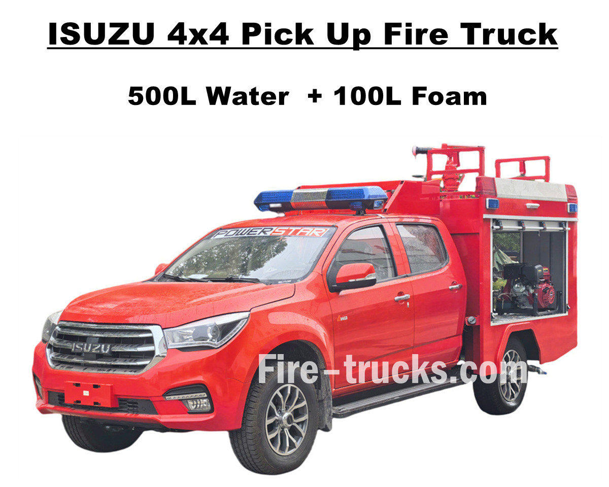
စက်ရုံရောင်းမည်။ ISUZU 4x4 offroad မီးငြှိမ်းသတ်ယာဉ် ISUZU TAGA ဘီးယက်ကိုယ်ထည်အားလုံးကို အသုံးပြု၍ ခက်ခဲသောလမ်းများအားလုံးကို စိန်ခေါ်ရန် အလွန်ကောင်းမွန်သော ပါဝါစနစ်ဖြင့် ပေါင်းစပ်ထားသည်။ Isuzu ပစ်ကပ်မီးသတ်ကယ်ဆယ်ရေးထရပ်တွင် 500 လီတာရေတိုင်ကီနှင့် 100 လီတာရေမြှုပ်တိုင်ကီအပါအဝင် stainless steel SS304 ပစ္စည်းများတင်သင်္ဘောတပ်ဆင်ထားပြီး၊ ပရော်ဖက်ရှင်နယ်အမှီအခိုကင်းသော မီးသတ်ပန့် JBQ4.5/9 ကို အနောက်ပန့်ခန်းတွင် တပ်ဆင်ထားရန်၊ ရှည်လျားသောလေဖြန်းမှုအကွာအဝေးနှင့် စိတ်ကြိုက်ထိန်းချုပ်မှုဘာသာစကားဖြင့် တပ်ဆင်ထားသည်။ ၎င်းသည် မတူညီသောလိုအပ်ချက်များကိုဖြည့်ဆည်းရန် ရွေးချယ်နိုင်သောဖွဲ့စည်းပုံအမျိုးမျိုးကိုလည်း ပေးဆောင်ပြီး ထိပ်မှရေထွက်ခြင်းအတွက် PS20 မီးသတ်မော်နီတာဖြင့် တပ်ဆင်ထားသည်။ ဤ ISUZU Pickup 143HP မီးစုပ်စက်ထရပ်ကားသည် မီးဘေးလုံခြုံရေးအတွက် ခိုင်မာသောအာမခံချက်ပေးထားပြီး အလွန်ကောင်းမွန်သောစွမ်းဆောင်ရည်နှင့် ပြောင်းလွယ်ပြင်လွယ်ကိုပြသထားသည်။ Isuzu မီးသတ်ကား၏ မူရင်းနှစ်ထပ် တက္ကစီသည် မီးငြှိမ်းသတ်ကိရိယာများကို တင်ဆောင်ရန်နှင့် ကောင်းမွန်သော မောင်းနှင်မှုစွမ်းဆောင်ရည်ကို ထိန်းသိမ်းရန် နေရာနှင့် အရည်အသွေးကို လုံလောက်စွာ ပံ့ပိုးပေးပါသည်။ အငှားယာဉ်တွင် မီးသတ်သမား ၅ ဦး ထားရှိနိုင်ပြီး ယာဉ်မောင်းသည် ရာသီဥတုအခြေအနေတွင် သက်တောင့်သက်သာနေနိုင်စေရန် လေအေးပေးစက် တပ်ဆင်ထားသည်။ ထို့အပြင် ISUZU 600L ရေမြှုပ်မီးသတ်အင်ဂျင်သည် အယ်လ်ဘေးနီးယားစျေးကွက်အတွက် အကောင်းဆုံး မီးသတ်ကယ်ဆယ်ရေးယာဉ်ဝန်ဆောင်မှုဖြစ်ကြောင်း အာမခံပါသည်။ နှင့် အောက်ဖော်ပြပါ User Manual များသည် ဘေးကင်းသော လုပ်ဆောင်ချက်နှင့် အလုပ်လုပ်ရန်အတွက် တပ်ဆင်ထားပါသည်။ » Ⅰ။ Isuzu Pick Up Fire Truck ၏ အဓိကအင်္ဂါရပ်များ ★ 105KW / 143HP အားကောင်းသော 4KH1 အင်ဂျင်၊ prblem မပါဘဲ 100,000 Km ။ ★ ISUZU TAGA အသစ်စက်စက် ပစ်ကပ်ကားအတွင်းခန်း၊ ဥရောပဒီဇိုင်း ★ Original double cabin၊ မီးသတ်သမား 5 ယောက်အတွက် သင့်လျော်သည်။ ★ လွတ်လပ်သော JBQ4.5/9 မီးသတ်ပန့်၊ အလွန်ယုံကြည်စိတ်ချရသော ★ ထိပ်တန်းတပ်ဆင်ထားသော PS8/20 မီးသတ်ပိုက်၊ အကြမ်းခံသောဝန်ဆောင်မှု » Ⅱ မီးတင်ဒါအကျဉ်းချုပ်ကို ကောက်ယူပါ- ISUZU 4x4 offroad AWD Water Foam Fire Fighting Truck သည် ရပ်ရွာ၊ သစ်တော၊ စက်ရုံစသည်ဖြင့် နေရာမျိုးစုံအတွက် ဝန်ဆောင်မှုပေးသော မြေပြင်မှ မီးသတ်ကားများဖြစ်သည်။ ၎င်းသည် offroad စွမ်းရည်နှင့် ကျဉ်းမြောင်းသောအသွင်အပြင်ကြောင့်၊ ဤ Isuzu Pickup မီးသတ်အင်ဂျင်သည် မစ်ရှင်အများအပြားကို ပြီးမြောက်အောင်မြင်စေပါသည်။ ကျွန်ုပ်တို့၏ မီးသတ်ကားများ ပိုမိုသင့်လျော်စေရန်၊ အောက်တွင် မတူညီသော သုံးစွဲသူများအတွက် ရွေးချယ်စရာများဖြစ်သည်။ ----- Tanker ပစ္စည်း : ကာဗွန်သံမဏိ၊ သံမဏိ၊ အလူမီနီယမ်အလွိုင်း၊ PP ပစ္စည်း ----- မီးသတ်ပိုက် : ရေနံတင်သင်္ဘောကိုယ်ထည်နှင့် ဂျက်လေယာဉ်အကွာအဝေးကို အခြေခံ၍ ရွေးချယ်နိုင်သော အမေရိကန် Darley အမှတ်တံဆိပ် ----- ရွေးချယ်နိုင်သည်- ပိုက်လိုင်း၊ ပိုက်ကြိုး၊ အလူမီနီယံလှေကား၊ ပူးတွဲမော်ဒယ် (တရုတ်၊ ဥရောပ၊ အမေရိကန် အမျိုးအစား) » Ⅲ။ ဆွဲဆောင်မှုရှိသော အသွင်အပြင် ISUZU 4x4 AWD မီးထရပ်ကားသည် အားကောင်းပြီး တုံ့ပြန်မှုရှိသော၊ မီးလောင်ကျွမ်းသည့်နေရာသို့ လျင်မြန်စွာရောက်ရှိနိုင်ပြီး ရှုပ်ထွေးသောမြေပြင်ကို အလွယ်တကူဖြတ်သန်းနိုင်သည်။ ထိပ်တန်းမီးသတ်အမြောက်သည် အကွာအဝေးနှင့် ကြီးမားသော စီးဆင်းမှုနှုန်းရှိပြီး မီတာ 50 ရှည်သော မီးသတ်ပိုက် ရစ်ပတ်သည် မီးအရင်းအမြစ်ကို တိကျစွာ ထိမှန်နိုင်ပြီး ထိထိရောက်ရောက် ဖုံးအုပ်ပြီး သီးခြားခွဲထုတ်နိုင်သည်။ ကယ်ဆယ်ရေး ကိရိယာအစုံအလင် တပ်ဆင်ထားသော ပစ်ကပ်မီးသတ်ယာဉ်...
အသေးစိတ်
ဆက်လက်ဖတ်ရှုပါ၊ သတင်းအချက်အလက်များကို စောင့်မျှော်ပါ၊ စာရင်းသွင်းပါ နှင့် သင်၏အမြင်များကို ကျွန်ုပ်တို့အား ပြောပြရန် ကြိုဆိုပါသည်။

 IPv6 ကွန်ယက်ကိုထောက်ခံသည်

 မြန်မာ
 English
 français
 Deutsch
 русский
 italiano
 español
 português
 Nederlands
 العربية
 日本語
日本語 한국의
한국의 Türkçe
 Melayu
 ไทย
ไทย Tiếng Việt
 Indonesia
  中文
中文 қазақ
қазақ Filipino
 српски